


7. SPECIAL ADJUSTMENT FUNCTIONS
7 - 23
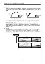
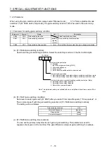
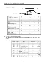
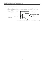
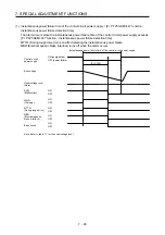
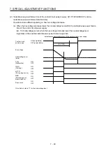
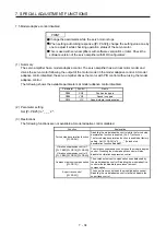
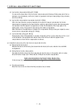
(b) Switching timing chart
After-switching gain
63.4%
CDT = 100 ms
Before-switching gain
Gain switching
Droop pulses
[pulse]
+CDL
-CDL
0
Command pulses
Droop pulses
Command pulses
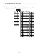
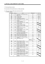
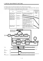
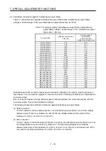
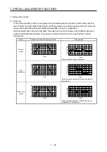
Load to motor inertia ratio
4.00
→
10.00
→
4.00
→
10.00
Position loop gain
120
→
84
→
120
→
84
Speed loop gain
3000
→
4000
→
3000
→
4000
Speed integral compensation
20
→
50
→
20
→
50
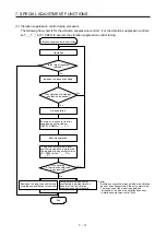
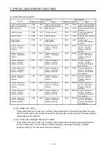
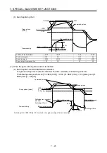
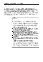
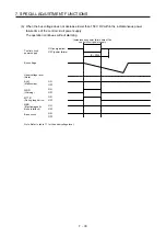
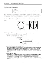
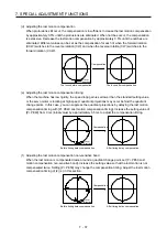
(3) When the gain switching time constant is disabled
(a) Switching time constant disabled was selected.
The gain switching time constant is disabled. The time constant is enabled at gain return.
The following example shows for [Pr. PB26 (CDP)] = 0103, [Pr. PB27 (CDL)] = 100 [pulse], and [Pr.
PB28 (CDT)] = 100 [ms].
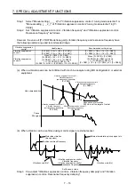
Command pulses
Droop pulses
+100 pulses
-100 pulses
0
Droop pulses [pulse]
Switching time constant
disabled
Switching at 0 ms
After-switching gain
Before-switching gain
Switching at [Pr. PB28 (CDT)] = 100 [ms] only when gain switching off (when returning)
CDT = 100 ms
63.4%
Switching at 0 ms
After-switching gain
Gain switching
Summary of Contents for MR-J4-100A(-RJ)
Page 19: ...10 MEMO ...
Page 75: ...1 FUNCTIONS AND CONFIGURATION 1 56 MEMO ...
Page 83: ...2 INSTALLATION 2 8 MEMO ...
Page 159: ...3 SIGNALS AND WIRING 3 76 MEMO ...
Page 203: ...4 STARTUP 4 44 MEMO ...
Page 351: ...7 SPECIAL ADJUSTMENT FUNCTIONS 7 40 MEMO ...
Page 365: ...8 TROUBLESHOOTING 8 14 MEMO ...
Page 387: ...9 DIMENSIONS 9 22 MEMO ...
Page 403: ...10 CHARACTERISTICS 10 16 MEMO ...
Page 553: ...12 ABSOLUTE POSITION DETECTION SYSTEM 12 30 MEMO ...
Page 567: ...13 USING STO FUNCTION 13 14 MEMO ...
Page 607: ...14 COMMUNICATION FUNCTION MITSUBISHI ELECTRIC GENERAL PURPOSE AC SERVO PROTOCOL 14 40 MEMO ...
Page 639: ...15 USING A LINEAR SERVO MOTOR 15 32 MEMO ...
Page 767: ...18 MR J4 03A6 RJ SERVO AMPLIFIER 18 84 MEMO ...
Page 856: ...APPENDIX App 41 ...
Page 905: ...MEMO ...


