


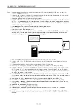
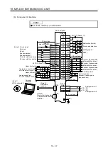
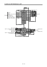

19. MR-D01 EXTENSION I/O UNIT
19 - 29
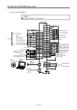
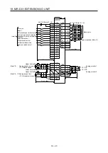
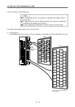
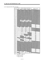
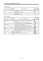
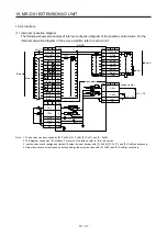
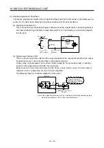
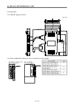
19.5.2 Connectors and pin assignment
POINT
The pin assignment of the connectors is as viewed from the cable connector
wiring section.
The CN30 connector is for manufacturer setting. This connector is attached on
the MR-D01 servo amplifier, but not for use.
For the pin assignment of the CN10 connector, refer to (2) in this section.
For details of each signal (device), refer to section 19.5.3.
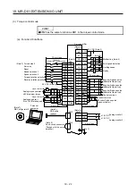
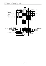
(1) Pin assignment
The following shows the front view of the servo amplifier for when MR-J4-10A-RJ and MR-D01 are used.
CN10
2
4
6
8
10
12
14
16
18
20
22
24
1
3
5
7
9
11
13
15
17
19
21
23
27
29
31
33
35
37
39
41
43
45
47
49
26
28
30
32
34
36
38
40
42
44
46
48
25
50
CN20
1
11
2
12
LG
OVC
3
13
4
14
5
6
8
10
7
9
16
18
20
15
17
19
OTLA
LG
P15R
N12R
For the pin assignment, refer to (2)
in this section.
OMO1
OMO2
LG
CN30
For
manufacturer
setting
Summary of Contents for MR-J4-100A(-RJ)
Page 19: ...10 MEMO ...
Page 75: ...1 FUNCTIONS AND CONFIGURATION 1 56 MEMO ...
Page 83: ...2 INSTALLATION 2 8 MEMO ...
Page 159: ...3 SIGNALS AND WIRING 3 76 MEMO ...
Page 203: ...4 STARTUP 4 44 MEMO ...
Page 351: ...7 SPECIAL ADJUSTMENT FUNCTIONS 7 40 MEMO ...
Page 365: ...8 TROUBLESHOOTING 8 14 MEMO ...
Page 387: ...9 DIMENSIONS 9 22 MEMO ...
Page 403: ...10 CHARACTERISTICS 10 16 MEMO ...
Page 553: ...12 ABSOLUTE POSITION DETECTION SYSTEM 12 30 MEMO ...
Page 567: ...13 USING STO FUNCTION 13 14 MEMO ...
Page 607: ...14 COMMUNICATION FUNCTION MITSUBISHI ELECTRIC GENERAL PURPOSE AC SERVO PROTOCOL 14 40 MEMO ...
Page 639: ...15 USING A LINEAR SERVO MOTOR 15 32 MEMO ...
Page 767: ...18 MR J4 03A6 RJ SERVO AMPLIFIER 18 84 MEMO ...
Page 856: ...APPENDIX App 41 ...
Page 905: ...MEMO ...


