

7. SPECIAL ADJUSTMENT FUNCTIONS
7 - 36
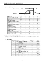
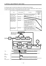
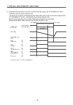
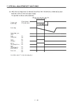
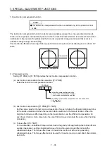
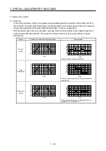
(d) Lost motion compensation timing ([Pr. PE49])
You can set the delay time of the lost motion compensation start timing with this parameter. When a
protrusion occurs belatedly, set the lost motion compensation timing corresponding to the protrusion
occurrence timing.
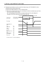
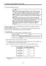
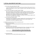
(e) Lost motion compensation non-sensitive band ([Pr. PE50])
When the travel direction reverses frequently around the zero speed, unnecessary lost motion
compensation is triggered by the travel direction switching. By setting the lost motion compensation
non-sensitive band, the speed is recognized as 0 when the fluctuation of the droop pulse is the
setting value or less. This prevents unnecessary lost motion compensation.
When the value of this parameter is changed, the compensation timing is changed. Adjust the value
of Lost motion compensation timing ([Pr. PE49]).
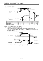
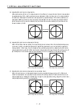
(f) Lost motion filter setting ([Pr. PE46])
Changing the value of this parameter is usually unnecessary. When a value other than 0.0 ms is set
in this parameter, the high-pass filter output value of the set time constant is applied to the
compensation and lost motion compensation continues.
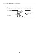
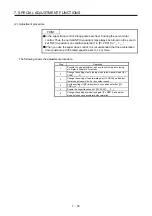
(2) Adjustment procedure of the lost motion compensation function
(a) Measuring the load current
Measure the load currents during the forward direction feed and reverse direction feed with MR
Configurator2.
(b) Setting the lost motion compensation
Calculate the friction torque from the measurement result of (2) (a) in this section and set a value
twice the friction torque in [Pr. PE44] and [Pr. PE45] as lost motion compensation.
Friction torque [%] =
2
|(load current during feed in the forward rotation direction [%]) -
(load current during feed in the reverse rotation direction [%])|
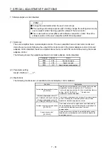
(c) Checking protrusions
Drive the servo motor and check that the protrusions are corrected.
Summary of Contents for MR-J4-100A(-RJ)
Page 19: ...10 MEMO ...
Page 75: ...1 FUNCTIONS AND CONFIGURATION 1 56 MEMO ...
Page 83: ...2 INSTALLATION 2 8 MEMO ...
Page 159: ...3 SIGNALS AND WIRING 3 76 MEMO ...
Page 203: ...4 STARTUP 4 44 MEMO ...
Page 351: ...7 SPECIAL ADJUSTMENT FUNCTIONS 7 40 MEMO ...
Page 365: ...8 TROUBLESHOOTING 8 14 MEMO ...
Page 387: ...9 DIMENSIONS 9 22 MEMO ...
Page 403: ...10 CHARACTERISTICS 10 16 MEMO ...
Page 553: ...12 ABSOLUTE POSITION DETECTION SYSTEM 12 30 MEMO ...
Page 567: ...13 USING STO FUNCTION 13 14 MEMO ...
Page 607: ...14 COMMUNICATION FUNCTION MITSUBISHI ELECTRIC GENERAL PURPOSE AC SERVO PROTOCOL 14 40 MEMO ...
Page 639: ...15 USING A LINEAR SERVO MOTOR 15 32 MEMO ...
Page 767: ...18 MR J4 03A6 RJ SERVO AMPLIFIER 18 84 MEMO ...
Page 856: ...APPENDIX App 41 ...
Page 905: ...MEMO ...


