


7. SPECIAL ADJUSTMENT FUNCTIONS
7 - 20
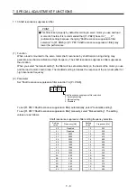
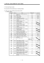
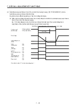
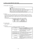
(c) [Pr. PB29 Load to motor inertia ratio after gain switching]
Set the load to motor inertia ratio after gain switching. If the load to motor inertia ratio does not
change, set it to the same value as [Pr. PB06 Load to motor inertia ratio].
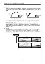
(d) [Pr. PB30 Position loop gain after gain switching], [Pr. PB31 Speed loop gain after gain switching],
and [Pr. PB32 Speed integral compensation after gain switching]
Set the values of after switching position loop gain, speed loop gain and speed integral
compensation.
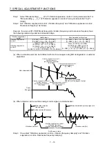
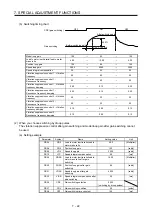
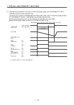
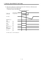
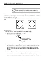
(e) Vibration suppression control after gain switching ([Pr. PB33] to [Pr. PB36]/[Pr. PB56] to [Pr. PB59]),
and [Pr. PB60 Model loop gain after gain switching]
The gain switching vibration suppression control and gain switching model loop gain are used only
with input device (CDP) on/off.
You can switch the vibration frequency, resonance frequency, vibration frequency damping,
resonance frequency damping, and model loop gain of the vibration suppression control 1 and
vibration suppression control 2.
Summary of Contents for MR-J4-100A(-RJ)
Page 19: ...10 MEMO ...
Page 75: ...1 FUNCTIONS AND CONFIGURATION 1 56 MEMO ...
Page 83: ...2 INSTALLATION 2 8 MEMO ...
Page 159: ...3 SIGNALS AND WIRING 3 76 MEMO ...
Page 203: ...4 STARTUP 4 44 MEMO ...
Page 351: ...7 SPECIAL ADJUSTMENT FUNCTIONS 7 40 MEMO ...
Page 365: ...8 TROUBLESHOOTING 8 14 MEMO ...
Page 387: ...9 DIMENSIONS 9 22 MEMO ...
Page 403: ...10 CHARACTERISTICS 10 16 MEMO ...
Page 553: ...12 ABSOLUTE POSITION DETECTION SYSTEM 12 30 MEMO ...
Page 567: ...13 USING STO FUNCTION 13 14 MEMO ...
Page 607: ...14 COMMUNICATION FUNCTION MITSUBISHI ELECTRIC GENERAL PURPOSE AC SERVO PROTOCOL 14 40 MEMO ...
Page 639: ...15 USING A LINEAR SERVO MOTOR 15 32 MEMO ...
Page 767: ...18 MR J4 03A6 RJ SERVO AMPLIFIER 18 84 MEMO ...
Page 856: ...APPENDIX App 41 ...
Page 905: ...MEMO ...


