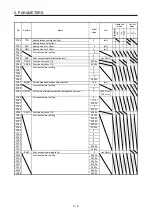
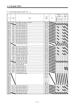
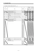
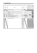


5. PARAMETERS
5 - 20
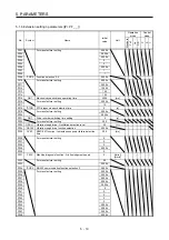
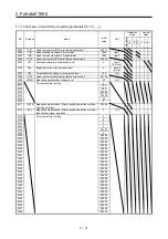
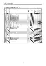
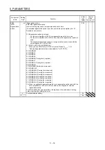
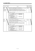
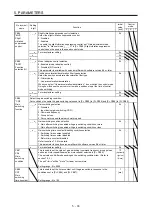
No./symbol/
name
Setting
digit
Function
Initial
value
[unit]
Control
mode
P S T
PA13
*PLSS
Command
pulse input
form
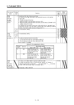
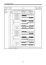
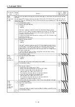
Table 5.3 Command input pulse train form selection
Setting
value
Pulse train form
Forward rotation
(positive direction)
command
Reverse rotation
(negative direction)
command
_ _ 1 0
Negative logic
Forward rotation
pulse train
(positive direction
pulse train)
Reverse rotation
pulse train
(negative direction
pulse train)
NP
PP
_ _ 1 1
Signed pulse train
PP
L
H
NP
_ _ 1 2
A-phase pulse
train
B-phase pulse
train
PP
NP
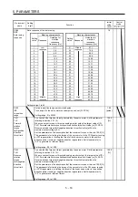
_ _ 0 0
Positive logic
Forward rotation
pulse train
(positive direction
pulse train)
Reverse rotation
pulse train
(negative direction
pulse train)
NP
PP
_ _ 0 1
Signed pulse train
L
H
PP
NP
_ _ 0 2
A-phase pulse
train
B-phase pulse
train
PP
NP
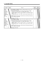
Arrows in the table indicate the timing of importing pulse trains. A-phase and B-phase pulse trains are imported after
they have been multiplied by 4.
Summary of Contents for MR-J4-100A(-RJ)
Page 19: ...10 MEMO ...
Page 75: ...1 FUNCTIONS AND CONFIGURATION 1 56 MEMO ...
Page 83: ...2 INSTALLATION 2 8 MEMO ...
Page 159: ...3 SIGNALS AND WIRING 3 76 MEMO ...
Page 203: ...4 STARTUP 4 44 MEMO ...
Page 351: ...7 SPECIAL ADJUSTMENT FUNCTIONS 7 40 MEMO ...
Page 365: ...8 TROUBLESHOOTING 8 14 MEMO ...
Page 387: ...9 DIMENSIONS 9 22 MEMO ...
Page 403: ...10 CHARACTERISTICS 10 16 MEMO ...
Page 553: ...12 ABSOLUTE POSITION DETECTION SYSTEM 12 30 MEMO ...
Page 567: ...13 USING STO FUNCTION 13 14 MEMO ...
Page 607: ...14 COMMUNICATION FUNCTION MITSUBISHI ELECTRIC GENERAL PURPOSE AC SERVO PROTOCOL 14 40 MEMO ...
Page 639: ...15 USING A LINEAR SERVO MOTOR 15 32 MEMO ...
Page 767: ...18 MR J4 03A6 RJ SERVO AMPLIFIER 18 84 MEMO ...
Page 856: ...APPENDIX App 41 ...
Page 905: ...MEMO ...


