


18. MR-J4-03A6(-RJ) SERVO AMPLIFIER
18 - 10
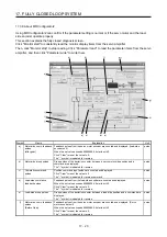
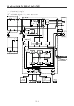
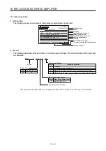
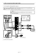
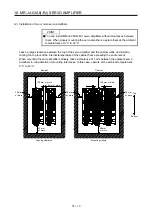
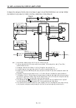
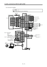
18.1.8 Configuration including peripheral equipment
CAUTION
Connecting a servo motor of the wrong axis to U, V, W, or CN2 of the servo
amplifier may cause a malfunction.
POINT
Equipment other than the servo amplifier and servo motor are optional or
recommended products.
Personal
computer
CN3
CN2
CNP1
MR Configurator2
24
0
PM
Relay
Circuit
protector
-
+
24 V DC
power
supply
+
-
48 V DC
power
supply
Circuit
protector
-
+
24 V DC
power
supply
PM 0
24
48 V DC main circuit power supply
24 V DC main circuit power supply
Servo motor
CN4
MR-BAT6V1SET-A
CNP1
(Note)
CN1
Junction terminal block
Note. Refer to section 18.3.2 for details.
Summary of Contents for MR-J4-100A(-RJ)
Page 19: ...10 MEMO ...
Page 75: ...1 FUNCTIONS AND CONFIGURATION 1 56 MEMO ...
Page 83: ...2 INSTALLATION 2 8 MEMO ...
Page 159: ...3 SIGNALS AND WIRING 3 76 MEMO ...
Page 203: ...4 STARTUP 4 44 MEMO ...
Page 351: ...7 SPECIAL ADJUSTMENT FUNCTIONS 7 40 MEMO ...
Page 365: ...8 TROUBLESHOOTING 8 14 MEMO ...
Page 387: ...9 DIMENSIONS 9 22 MEMO ...
Page 403: ...10 CHARACTERISTICS 10 16 MEMO ...
Page 553: ...12 ABSOLUTE POSITION DETECTION SYSTEM 12 30 MEMO ...
Page 567: ...13 USING STO FUNCTION 13 14 MEMO ...
Page 607: ...14 COMMUNICATION FUNCTION MITSUBISHI ELECTRIC GENERAL PURPOSE AC SERVO PROTOCOL 14 40 MEMO ...
Page 639: ...15 USING A LINEAR SERVO MOTOR 15 32 MEMO ...
Page 767: ...18 MR J4 03A6 RJ SERVO AMPLIFIER 18 84 MEMO ...
Page 856: ...APPENDIX App 41 ...
Page 905: ...MEMO ...


