
18. MR-J4-03A6(-RJ) SERVO AMPLIFIER
18 - 58
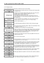
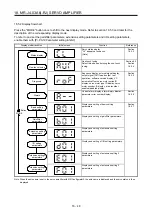
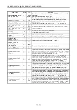
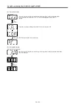
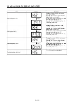
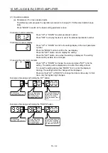
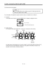
18.5.5 Diagnostic mode
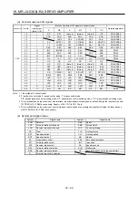
Name Display
Description
Sequence
Not ready
Indicates that the servo amplifier is being
initialized or an alarm has occurred.
Ready
Indicates that the servo was switched on after
completion of initialization and the servo
amplifier is ready to operate.
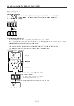
Drive recorder enabled/disabled display
Drive recorder enabled
When an alarm occurs in the status, the drive
recorder will operate and write the status of
occurrence.
Drive recorder disabled
The drive recorder will not operate on the
following conditions.
1. You are using the graph function of MR
Configurator2.
2. You are using the machine analyzer
function.
3. [Pr. PF21] is set to "-1".
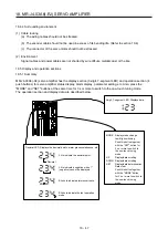
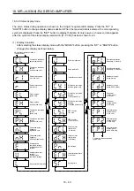
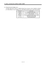
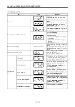
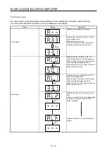
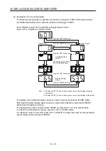
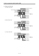
External I/O signal display
Refer to section 18.5.8.
This indicates the on/off status of external I/O
signal.
The upper segments correspond to the input
signals and the lower segments to the output
signals.
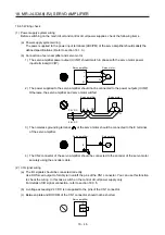
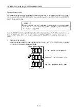
Output signal (DO) forced output
This allows digital output signal to be
switched on/off forcibly.
For details, refer to section 18.5.9.
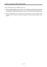
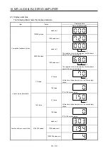
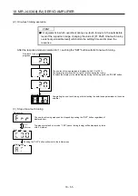
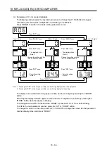
Test operation
mode
JOG operation
JOG operation can be performed when there
is no command from an external controller.
For details, refer to section 18.5.10 (2).
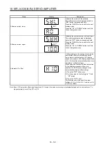
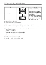
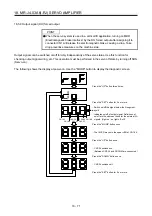
Positioning operation
Positioning operation can be performed when
there is no command from an external
controller.
MR Configurator2 is required to perform
positioning operation.
For details, refer to section 4.5.9 (3).
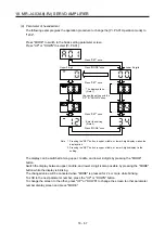
Motor-less operation
Without connecting the servo motor, output
signals or status display monitoring can be
provided in response to the input device as if
the servo motor is actually running.
For details, refer to section 4.5.9 (4).
Machine analyzer operation
Merely connecting the servo amplifier allows
the resonance point of the mechanical system
to be measured.
MR Configurator2 is required to perform
machine analyzer operation.
Refer to section 11.7 for details.
For manufacturer adjustment
This is for manufacturer adjustment.
Summary of Contents for MR-J4-100A(-RJ)
Page 19: ...10 MEMO ...
Page 75: ...1 FUNCTIONS AND CONFIGURATION 1 56 MEMO ...
Page 83: ...2 INSTALLATION 2 8 MEMO ...
Page 159: ...3 SIGNALS AND WIRING 3 76 MEMO ...
Page 203: ...4 STARTUP 4 44 MEMO ...
Page 351: ...7 SPECIAL ADJUSTMENT FUNCTIONS 7 40 MEMO ...
Page 365: ...8 TROUBLESHOOTING 8 14 MEMO ...
Page 387: ...9 DIMENSIONS 9 22 MEMO ...
Page 403: ...10 CHARACTERISTICS 10 16 MEMO ...
Page 553: ...12 ABSOLUTE POSITION DETECTION SYSTEM 12 30 MEMO ...
Page 567: ...13 USING STO FUNCTION 13 14 MEMO ...
Page 607: ...14 COMMUNICATION FUNCTION MITSUBISHI ELECTRIC GENERAL PURPOSE AC SERVO PROTOCOL 14 40 MEMO ...
Page 639: ...15 USING A LINEAR SERVO MOTOR 15 32 MEMO ...
Page 767: ...18 MR J4 03A6 RJ SERVO AMPLIFIER 18 84 MEMO ...
Page 856: ...APPENDIX App 41 ...
Page 905: ...MEMO ...


