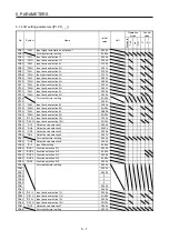
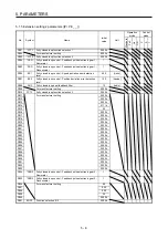
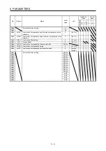
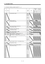


5. PARAMETERS
5 - 17
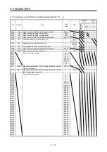
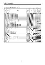
No./symbol/
name
Setting
digit
Function
Initial
value
[unit]
Control
mode
P S T
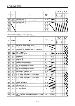
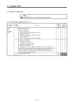
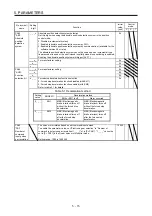
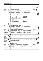
PA08
ATU
Auto tuning
mode
_ _ _ x Gain adjustment mode selection
Select the gain adjustment mode.
0: 2 gain adjustment mode 1 (interpolation mode)
1: Auto tuning mode 1
2: Auto tuning mode 2
3: Manual mode
4: 2 gain adjustment mode 2
Refer to table 5.2 for details.
1h
_ _ x _ For manufacturer setting
0h
_ x _ _
0h
x _ _ _
0h
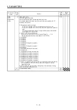
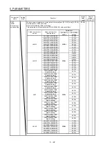
Table 5.2 Gain adjustment mode selection
Setting
value
Gain adjustment
mode
Automatically adjusted parameter
_ _ _ 0 2 gain adjustment
mode 1
(interpolation mode)
[Pr. PB06 Load to motor inertia ratio]
[Pr. PB08 Position loop gain]
[Pr. PB09 Speed loop gain]
[Pr. PB10 Speed integral compensation]
_ _ _ 1 Auto tuning mode 1
[Pr. PB06 Load to motor inertia ratio]
[Pr. PB07 Model loop gain]
[Pr. PB08 Position loop gain]
[Pr. PB09 Speed loop gain]
[Pr. PB10 Speed integral compensation]
_ _ _ 2 Auto tuning mode 2
[Pr. PB07 Model loop gain]
[Pr. PB08 Position loop gain]
[Pr. PB09 Speed loop gain]
[Pr. PB10 Speed integral compensation]
_ _ _ 3 Manual mode
_ _ _ 4 2 gain adjustment
mode 2
[Pr. PB08 Position loop gain]
[Pr. PB09 Speed loop gain]
[Pr. PB10 Speed integral compensation]
Summary of Contents for MR-J4-100A(-RJ)
Page 19: ...10 MEMO ...
Page 75: ...1 FUNCTIONS AND CONFIGURATION 1 56 MEMO ...
Page 83: ...2 INSTALLATION 2 8 MEMO ...
Page 159: ...3 SIGNALS AND WIRING 3 76 MEMO ...
Page 203: ...4 STARTUP 4 44 MEMO ...
Page 351: ...7 SPECIAL ADJUSTMENT FUNCTIONS 7 40 MEMO ...
Page 365: ...8 TROUBLESHOOTING 8 14 MEMO ...
Page 387: ...9 DIMENSIONS 9 22 MEMO ...
Page 403: ...10 CHARACTERISTICS 10 16 MEMO ...
Page 553: ...12 ABSOLUTE POSITION DETECTION SYSTEM 12 30 MEMO ...
Page 567: ...13 USING STO FUNCTION 13 14 MEMO ...
Page 607: ...14 COMMUNICATION FUNCTION MITSUBISHI ELECTRIC GENERAL PURPOSE AC SERVO PROTOCOL 14 40 MEMO ...
Page 639: ...15 USING A LINEAR SERVO MOTOR 15 32 MEMO ...
Page 767: ...18 MR J4 03A6 RJ SERVO AMPLIFIER 18 84 MEMO ...
Page 856: ...APPENDIX App 41 ...
Page 905: ...MEMO ...


