

15. USING A LINEAR SERVO MOTOR
15 - 18
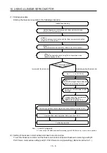
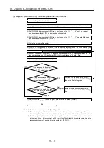
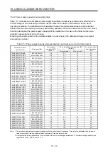
2) Specify the setting value that is an approximately 70% of the value set when [AL. 50 Overload 1],
[AL. 51 Overload 2], [AL. 33 Overvoltage], [AL. E1 Overload warning 1], and [AL. EC Overload
warning 2] occurred as the final setting value. However, if [AL. 27 Initial magnetic pole detection
error] occurs with this value, specify a value intermediate between the value set at [AL. 50
Overload 1], [AL. 51 Overload 2], [AL. 33 Overvoltage], [AL. E1 Overload warning 1], and [AL. EC
Overload warning 2] and the value set at the magnetic pole detection alarm as the final setting
value.
3) Perform the magnetic pole detection again with the final setting value to check there is no
problem.
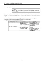
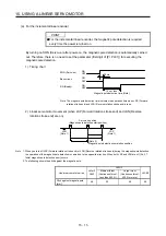
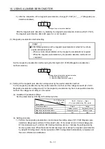
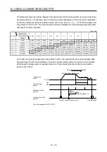
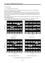
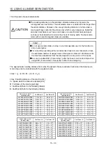
(c) Setting example
Occurring
Not occurring
Linear encoder magnetic
pole detection
[Pr. PL09] setting
Alarm
An alarm has occurred
when the setting value
of [Pr. PL09] is set to "70".
While increasing the setting value of [Pr. PL09], carry out the
magnetic pole detection repeatedly.
30
35
40
45
65
70
In this example, the final setting value of [Pr. PL09] is 49 (Setting value at the alarm occurrence = 70
× 0.7).
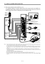
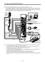
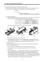
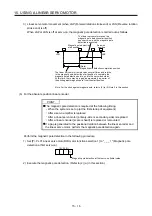
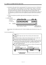
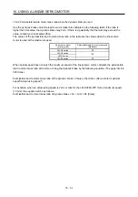
15.3.3 Home position return
POINT
Change the third digit value of [Pr. PL01] according to the linear encoder
resolution.
The incremental linear encoder and the absolute position linear encoder have
different reference home positions at the home position return.
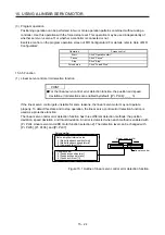
For the linear encoder, a home position (reference mark) of the linear encoder is
necessary in the home position return direction. In addition, install a dog so that
the mover passes the dog, decelerates to the creep speed, and passes the
home position (reference mark).
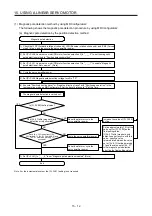
When you configure as follows, move the mover to LSN with JOG operation and
perform home position to perform it in safe.
LSN
LSP
Home position of linear encoder (reference mark)
Home position return direction
Non-returnable area:
Home position return cannot be performed
when started from this area.
Returnable area:
Home position return can be performed
when started from this area.
Dog
Summary of Contents for MR-J4-100A(-RJ)
Page 19: ...10 MEMO ...
Page 75: ...1 FUNCTIONS AND CONFIGURATION 1 56 MEMO ...
Page 83: ...2 INSTALLATION 2 8 MEMO ...
Page 159: ...3 SIGNALS AND WIRING 3 76 MEMO ...
Page 203: ...4 STARTUP 4 44 MEMO ...
Page 351: ...7 SPECIAL ADJUSTMENT FUNCTIONS 7 40 MEMO ...
Page 365: ...8 TROUBLESHOOTING 8 14 MEMO ...
Page 387: ...9 DIMENSIONS 9 22 MEMO ...
Page 403: ...10 CHARACTERISTICS 10 16 MEMO ...
Page 553: ...12 ABSOLUTE POSITION DETECTION SYSTEM 12 30 MEMO ...
Page 567: ...13 USING STO FUNCTION 13 14 MEMO ...
Page 607: ...14 COMMUNICATION FUNCTION MITSUBISHI ELECTRIC GENERAL PURPOSE AC SERVO PROTOCOL 14 40 MEMO ...
Page 639: ...15 USING A LINEAR SERVO MOTOR 15 32 MEMO ...
Page 767: ...18 MR J4 03A6 RJ SERVO AMPLIFIER 18 84 MEMO ...
Page 856: ...APPENDIX App 41 ...
Page 905: ...MEMO ...


