

17. FULLY CLOSED LOOP SYSTEM
17 - 22
17.3.7 Absolute position detection system under fully closed loop system
An absolute type linear encoder is necessary to configure an absolute position detection system under fully
closed loop control using a linear encoder. In this case, the encoder battery (MR-BAT6V1SET) need not be
installed to the servo amplifier. When an rotary encoder is used, an absolute position detection system can
be configured by installing the encoder battery (MR-BAT6V1SET) to the servo amplifier. In this case, the
battery life will be shorter because the power consumption is increased as the power is supplied to the two
encoders of motor side and load side.
For the absolute position detection system with linear encoder, the restrictions mentioned in this section
apply. Enable the absolute position detection system with [Pr. PA03 Absolute position detection system] and
use this servo within the following restrictions.
(1) Using conditions
(a) Use an absolute type linear encoder with the load-side encoder.
(b) Select Always fully closed loop ([Pr. PA01] = _ _ 1 _ and [Pr. PE01] = _ _ _ 0).
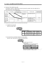
(2) Absolute position detection range using encoder
Encoder type
Absolute position detection enabled range
Linear encoder (serial
interface)
Movable distance range of linear encoder (within 32-bit absolute position data)
(3) Alarm detection
The absolute position-related alarm ([AL. 25]) and warnings (AL. 92] and [AL. 9F]) are not detected.
(4) Absolute position data transfer to controller
It is the same process as rotary servo motors. (Refer to section 12.8.)
Summary of Contents for MR-J4-100A(-RJ)
Page 19: ...10 MEMO ...
Page 75: ...1 FUNCTIONS AND CONFIGURATION 1 56 MEMO ...
Page 83: ...2 INSTALLATION 2 8 MEMO ...
Page 159: ...3 SIGNALS AND WIRING 3 76 MEMO ...
Page 203: ...4 STARTUP 4 44 MEMO ...
Page 351: ...7 SPECIAL ADJUSTMENT FUNCTIONS 7 40 MEMO ...
Page 365: ...8 TROUBLESHOOTING 8 14 MEMO ...
Page 387: ...9 DIMENSIONS 9 22 MEMO ...
Page 403: ...10 CHARACTERISTICS 10 16 MEMO ...
Page 553: ...12 ABSOLUTE POSITION DETECTION SYSTEM 12 30 MEMO ...
Page 567: ...13 USING STO FUNCTION 13 14 MEMO ...
Page 607: ...14 COMMUNICATION FUNCTION MITSUBISHI ELECTRIC GENERAL PURPOSE AC SERVO PROTOCOL 14 40 MEMO ...
Page 639: ...15 USING A LINEAR SERVO MOTOR 15 32 MEMO ...
Page 767: ...18 MR J4 03A6 RJ SERVO AMPLIFIER 18 84 MEMO ...
Page 856: ...APPENDIX App 41 ...
Page 905: ...MEMO ...


