

7. SPECIAL ADJUSTMENT FUNCTIONS
7 - 35
7.6 Lost motion compensation function
POINT
The lost motion compensation function is enabled only in the position control
mode.
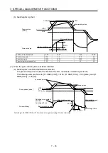
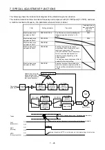
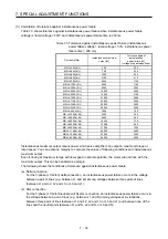
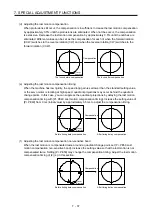
The lost motion compensation function corrects response delays (caused by a non-sensitive band due to
friction, twist, expansion, and backlash) caused when the machine travel direction is reversed. This function
contributes to improvement for protrusions that occur at a quadrant change and streaks that occur at a
quadrant change during circular cutting.
This function is effective when a high follow-up performance is required such as drawing an arc with an X-Y
table.
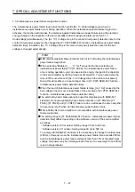
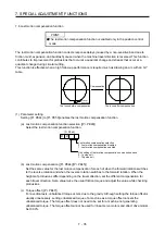
The locus before compensation
The locus after compensation
Compensation
Travel
direction
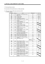
(1) Parameter setting
Setting [Pr. PE44] to [Pr. PE50] enables the lost motion compensation function.
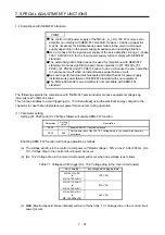
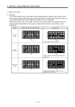
(a) Lost motion compensation function selection ([Pr. PE48])
Select the lost motion compensation function.
Lost motion compensation selection
0: Lost motion compensation disabled
1: Lost motion compensation enabled
0
Unit setting of lost motion compensation non-sensitive band
0: 1 pulse unit
1: 1 kpulse unit
[Pr. PE48]
0
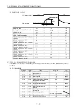
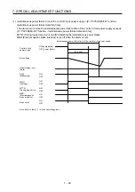
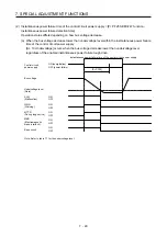
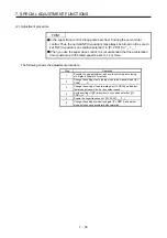
(b) Lost motion compensation ([Pr. PE44]/[Pr. PE45])
Set the same value for the lost motion compensation for each of when the forward rotation switches
to the reverse rotation and when the reverse rotation switches to the forward rotation. When the
heights of protrusions differ depending on the travel direction, set the different compensation for
each travel direction. Set a value twice the usual friction torque and adjust the value while checking
protrusions.
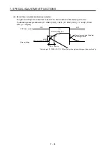
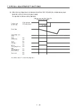
(c) Torque offset ([Pr. PE47])
For a vertical axis, unbalanced torque occurs due to the gravity. Although setting the torque offset is
usually unnecessary, setting unbalanced torque of a machine as a torque offset cancels the
unbalanced torque. The torque offset does not need to be set for a machine not generating
unbalanced torque. The torque offset cannot be used for linear servo motors and direct drive motors.
Set 0.00%.
Summary of Contents for MR-J4-100A(-RJ)
Page 19: ...10 MEMO ...
Page 75: ...1 FUNCTIONS AND CONFIGURATION 1 56 MEMO ...
Page 83: ...2 INSTALLATION 2 8 MEMO ...
Page 159: ...3 SIGNALS AND WIRING 3 76 MEMO ...
Page 203: ...4 STARTUP 4 44 MEMO ...
Page 351: ...7 SPECIAL ADJUSTMENT FUNCTIONS 7 40 MEMO ...
Page 365: ...8 TROUBLESHOOTING 8 14 MEMO ...
Page 387: ...9 DIMENSIONS 9 22 MEMO ...
Page 403: ...10 CHARACTERISTICS 10 16 MEMO ...
Page 553: ...12 ABSOLUTE POSITION DETECTION SYSTEM 12 30 MEMO ...
Page 567: ...13 USING STO FUNCTION 13 14 MEMO ...
Page 607: ...14 COMMUNICATION FUNCTION MITSUBISHI ELECTRIC GENERAL PURPOSE AC SERVO PROTOCOL 14 40 MEMO ...
Page 639: ...15 USING A LINEAR SERVO MOTOR 15 32 MEMO ...
Page 767: ...18 MR J4 03A6 RJ SERVO AMPLIFIER 18 84 MEMO ...
Page 856: ...APPENDIX App 41 ...
Page 905: ...MEMO ...


