

3. SIGNALS AND WIRING
3 - 40
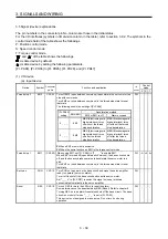
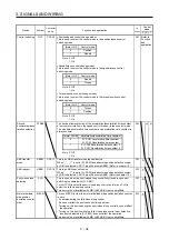
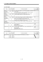
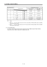
3.6 Detailed explanation of signals
3.6.1 Position control mode
POINT
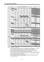
Adjust the logic of a positioning module and command pulse as follows.
MELSEC iQ-R series/MELSEC-Q series/MELSEC-L series positioning
module
Signal type
Command pulse logic setting
Positioning module
Pr. 23 setting
MR-J4-_A_(-RJ) servo
amplifier [Pr. PA13] setting
Open-collector type
Positive logic
Positive logic (_ _ 0 _)
Negative logic
Negative logic (_ _ 1 _)
Differential line driver type
Positive logic (Note)
Negative logic (_ _ 1 _)
Negative logic (Note)
Positive logic (_ _ 0 _)
Note.
For MELSEC iQ-R series, MELSEC-Q series and MELSEC-L series, the logic means N-side
waveform. Therefore, reverse the input pulse logic of the servo amplifier.
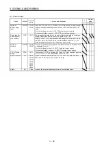
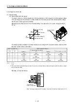
MELSEC-F series positioning module
Signal type
Command pulse logic setting
Positioning module (fixed)
MR-J4-_A_(-RJ) servo
amplifier
[Pr. PA13] setting
Open-collector
Differential line driver
Negative logic
Negative logic (_ _ 1 _)
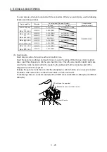
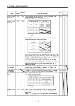
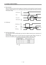
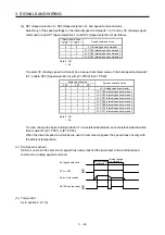
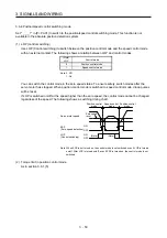
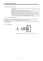
(1) Pulse train input
(a) Input pulse waveform selection
You can input command pulses in any of three different forms, and can choose positive or negative
logic. Set the command pulse train form in [Pr. PA13]. Refer to section 5.2.1 for details.
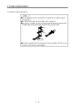
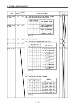
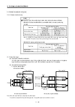
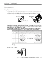
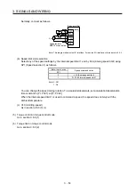
(b) Connection and waveform
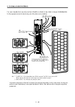
1) Open-collector type
Connect as follows.
1.2 k
Ω
Approx.
1.2 k
Ω
Approx.
SD
Servo amplifier
OPC
PP
NP
DOCOM
24 V DC
(Note)
Servo amplifier
PP2
PG
V
CES
≤
1.0 V
I
CEO
≤
100
μ
A
(Note)
(Note)
Approx. 20 mA
Approx. 20 mA
NP2
SD
NG
V
CES
≤
1.0 V
I
CEO
≤
100
μ
A
24 V DC ± 10%
500 mA
Approx.
1.2 k
Ω
Approx.
1.2 k
Ω
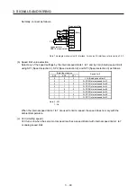
For sink input interface
For source input interface
Note. Pulse train input interface is comprised of a photocoupler.
If a resistor is connected to the pulse train signal line, it may malfunction due to reduction in current.
Summary of Contents for MR-J4-100A(-RJ)
Page 19: ...10 MEMO ...
Page 75: ...1 FUNCTIONS AND CONFIGURATION 1 56 MEMO ...
Page 83: ...2 INSTALLATION 2 8 MEMO ...
Page 159: ...3 SIGNALS AND WIRING 3 76 MEMO ...
Page 203: ...4 STARTUP 4 44 MEMO ...
Page 351: ...7 SPECIAL ADJUSTMENT FUNCTIONS 7 40 MEMO ...
Page 365: ...8 TROUBLESHOOTING 8 14 MEMO ...
Page 387: ...9 DIMENSIONS 9 22 MEMO ...
Page 403: ...10 CHARACTERISTICS 10 16 MEMO ...
Page 553: ...12 ABSOLUTE POSITION DETECTION SYSTEM 12 30 MEMO ...
Page 567: ...13 USING STO FUNCTION 13 14 MEMO ...
Page 607: ...14 COMMUNICATION FUNCTION MITSUBISHI ELECTRIC GENERAL PURPOSE AC SERVO PROTOCOL 14 40 MEMO ...
Page 639: ...15 USING A LINEAR SERVO MOTOR 15 32 MEMO ...
Page 767: ...18 MR J4 03A6 RJ SERVO AMPLIFIER 18 84 MEMO ...
Page 856: ...APPENDIX App 41 ...
Page 905: ...MEMO ...


