

17. FULLY CLOSED LOOP SYSTEM
17 - 24
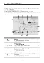
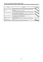
Symbol Name
Explanation
Unit
g)
Encoder information
The load-side encoder information is displayed.
The display contents differ depending on the load-side encoder type.
ID: The ID No. of the load-side encoder is displayed.
Data 1: For the incremental type linear encoder, the counter from powering on is
displayed. For the absolute position type linear encoder, the absolute
position data is displayed.
Data 2: For the incremental type linear encoder, the distance (number of pulses)
from the reference mark (Z-phase) is displayed. For the absolute position
type linear encoder, "00000000" is displayed.
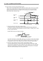
h)
Polarity
For address increasing direction in the servo motor CCW, it is indicated as "+" and for
address decreasing direction in the servo motor CCW, as "-".
i)
Z-phase pass status
If the fully closed loop system is "disabled", the Z-phase pass status of the servo motor
encoder is displayed. If the fully closed loop system is "Enabled" or "Semi closed loop
control/fully closed loop control switching", the Z-phase pass status of the load-side
encoder is displayed.
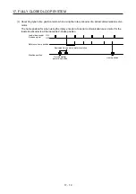
j)
Fully closed loop changing
device
Only if the fully closed loop system is "Semi closed loop control/fully closed loop control
switching", the device is displayed.
The state of the semi closed loop control/fully closed loop control switching signal and
the inside state during selection are displayed.
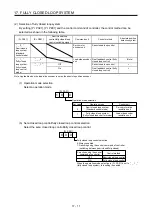
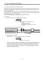
k) Parameter
(Feedback
pulse electronic gear)
The feedback pulse electronic gears ([Pr. PE04], [Pr. PE05], [Pr. PE34], and [Pr. PE35])
are displayed/set for servo motor encoder pulses in this parameter. (Refer to section
17.3.1 (5).)
l)
Parameter (Dual feedback
filter)
The band of [Pr. PE08 Fully closed loop dual feedback filter] is displayed/set in this
parameter.
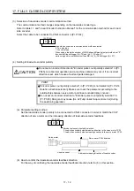
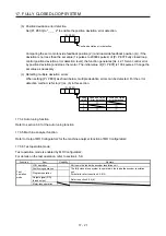
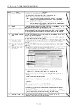
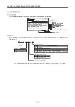
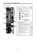
m)
Parameter (fully closed
loop function)
The parameter for the fully closed loop control is displayed or set.
Click "Parameter setting" button to display the "Fully closed loop control-Basic" window.
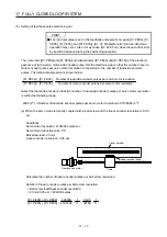
1)
2)
3)
4)
5)
1) Fully closed loop function selection ([Pr. PE01])
"Always valid" or "Changing by input signal (CLD)" is selected here.
2) Setting of feedback pulse electronic gear ([Pr. PE04], [Pr. PE05], [Pr. PE34], [Pr.
PE35])
Setting of feedback pulse electronic gear
3) Load-side encoder cable communication method selection ([Pr. PC44])
This is used to select a load-side encoder cable to be connected to the CN2L
connector.
4) Encoder pulse count polarity selection ([Pr. PC45])
Polarity of the load-side encoder cable information is selected.
5) Selection of A/B/Z-phase input interface encoder Z-phase connection judgment
function ([Pr. PC45])
Select the non-signal detection status for the pulse train signal from the A/B/Z-phase
input interface encoder used as a linear encoder or load-side encoder.
This function is enabled only when you use an A/B/Z-phase input interface encoder.
n)
Parameter (electronic gear) Electronic gear ([Pr. PA05], [Pr. PA06], [Pr. PA07], [Pr. PA13], [Pr. PA21])
This is used to set parameters for the electronic gear.
Summary of Contents for MR-J4-100A(-RJ)
Page 19: ...10 MEMO ...
Page 75: ...1 FUNCTIONS AND CONFIGURATION 1 56 MEMO ...
Page 83: ...2 INSTALLATION 2 8 MEMO ...
Page 159: ...3 SIGNALS AND WIRING 3 76 MEMO ...
Page 203: ...4 STARTUP 4 44 MEMO ...
Page 351: ...7 SPECIAL ADJUSTMENT FUNCTIONS 7 40 MEMO ...
Page 365: ...8 TROUBLESHOOTING 8 14 MEMO ...
Page 387: ...9 DIMENSIONS 9 22 MEMO ...
Page 403: ...10 CHARACTERISTICS 10 16 MEMO ...
Page 553: ...12 ABSOLUTE POSITION DETECTION SYSTEM 12 30 MEMO ...
Page 567: ...13 USING STO FUNCTION 13 14 MEMO ...
Page 607: ...14 COMMUNICATION FUNCTION MITSUBISHI ELECTRIC GENERAL PURPOSE AC SERVO PROTOCOL 14 40 MEMO ...
Page 639: ...15 USING A LINEAR SERVO MOTOR 15 32 MEMO ...
Page 767: ...18 MR J4 03A6 RJ SERVO AMPLIFIER 18 84 MEMO ...
Page 856: ...APPENDIX App 41 ...
Page 905: ...MEMO ...


