


8
17.3.1 Startup ................................................................................................................................... 17-10
17.3.2 Home position return ............................................................................................................. 17-17
17.3.3 Fully closed loop control error detection functions................................................................ 17-20
17.3.4 Auto tuning function .............................................................................................................. 17-21
17.3.5 Machine analyzer function .................................................................................................... 17-21
17.3.6 Test operation mode ............................................................................................................. 17-21
17.3.7 Absolute position detection system under fully closed loop system ..................................... 17-22
17.3.8 About MR Configurator2 ....................................................................................................... 17-23
18. MR-J4-03A6(-RJ) SERVO AMPLIFIER
18- 1 to 18-84
18.1 Functions and configuration ......................................................................................................... 18- 1
18.1.1 Summary ................................................................................................................................ 18- 1
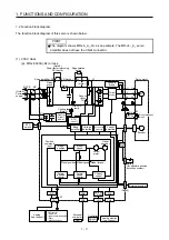
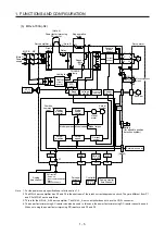
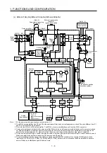
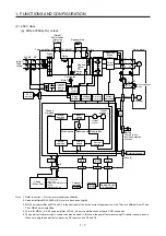
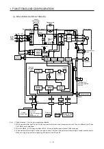
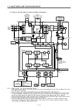
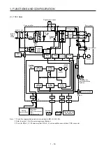
18.1.2 Function block diagram .......................................................................................................... 18- 2
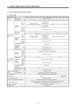
18.1 3 Servo amplifier standard specifications ................................................................................. 18- 3
18.1.4 Combinations of servo amplifiers and servo motors .............................................................. 18- 4
18.1.5 Function list ............................................................................................................................ 18- 5
18.1.6 Model definition ...................................................................................................................... 18- 8
18.1.7 Parts identification .................................................................................................................. 18- 9
18.1.8 Configuration including peripheral equipment ...................................................................... 18-10
18.2 Installation .................................................................................................................................... 18-11
18.2.1 Installation direction and clearances ..................................................................................... 18-12
18.2.2 Installation by DIN rail ........................................................................................................... 18-14
18.3 Signals and wiring ........................................................................................................................ 18-16
18.3.1 Input power supply circuit ..................................................................................................... 18-17
18.3.2 Explanation of power supply system ..................................................................................... 18-19
18.3.3 Selection of main circuit power supply/control circuit power supply ..................................... 18-22
18.3.4 Power-on sequence .............................................................................................................. 18-22
18.3.5 I/O signal connection example .............................................................................................. 18-23
18.3.6 Connectors and pin assignment ........................................................................................... 18-31
18.3.7 Signal (device) explanations ................................................................................................. 18-34
18.3.8 Alarm occurrence timing chart .............................................................................................. 18-38
18.3.9 Interfaces (Internal connection diagram) .............................................................................. 18-40
18.3.10 Grounding ........................................................................................................................... 18-42
18.4 Startup ......................................................................................................................................... 18-43
18.4.1 Startup procedure ................................................................................................................. 18-44
18.4.2 Troubleshooting when "24 V ERROR" lamp turns on ........................................................... 18-45
18.4.3 Wiring check .......................................................................................................................... 18-46
18.4.4 Surrounding environment ...................................................................................................... 18-47
18.5 Display and operation sections .................................................................................................... 18-47
18.5.1 Summary ............................................................................................................................... 18-47
18.5.2 Display flowchart ................................................................................................................... 18-48
18.5.3 Status display mode .............................................................................................................. 18-49
18.5.4 One-touch tuning
................................................................................................................... 18-54
18.5.5 Diagnostic mode ................................................................................................................... 18-58
18.5.6 Alarm mode ........................................................................................................................... 18-61
18.5.7 Parameter mode ................................................................................................................... 18-63
18.5.8 External I/O signal display..................................................................................................... 18-68
18.5.9 Output signal (DO) forced output .......................................................................................... 18-71
18.5.10 Test operation mode ........................................................................................................... 18-72
18.6 Dimensions .................................................................................................................................. 18-74
Summary of Contents for MR-J4-100A(-RJ)
Page 19: ...10 MEMO ...
Page 75: ...1 FUNCTIONS AND CONFIGURATION 1 56 MEMO ...
Page 83: ...2 INSTALLATION 2 8 MEMO ...
Page 159: ...3 SIGNALS AND WIRING 3 76 MEMO ...
Page 203: ...4 STARTUP 4 44 MEMO ...
Page 351: ...7 SPECIAL ADJUSTMENT FUNCTIONS 7 40 MEMO ...
Page 365: ...8 TROUBLESHOOTING 8 14 MEMO ...
Page 387: ...9 DIMENSIONS 9 22 MEMO ...
Page 403: ...10 CHARACTERISTICS 10 16 MEMO ...
Page 553: ...12 ABSOLUTE POSITION DETECTION SYSTEM 12 30 MEMO ...
Page 567: ...13 USING STO FUNCTION 13 14 MEMO ...
Page 607: ...14 COMMUNICATION FUNCTION MITSUBISHI ELECTRIC GENERAL PURPOSE AC SERVO PROTOCOL 14 40 MEMO ...
Page 639: ...15 USING A LINEAR SERVO MOTOR 15 32 MEMO ...
Page 767: ...18 MR J4 03A6 RJ SERVO AMPLIFIER 18 84 MEMO ...
Page 856: ...APPENDIX App 41 ...
Page 905: ...MEMO ...


