

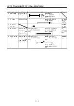

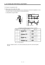

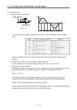
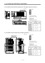
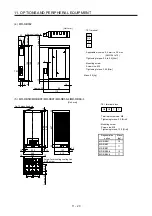
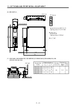

11. OPTIONS AND PERIPHERAL EQUIPMENT
11 - 13
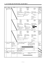
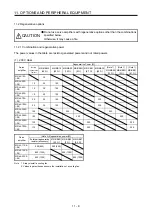
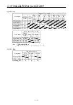
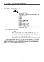
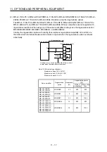
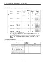
11.2.3 Parameter setting
Set [Pr. PA02] according to the option to be used.
Regenerative option selection
00: Regenerative option is not used.
For servo amplifier of 100 W, regenerative resistor is not used.
For servo amplifier of 0.2 kW to 7 kW, built-in regenerative resistor is used.
Supplied regenerative resistors or regenerative option is used with the servo
amplifier of 11 kW to 22 kW.
01: FR-BU2/FR-BU2-H/FR-RC/FR-RC-H/FR-CV/FR-CV-H
02: MR-RB032
03: MR-RB12
04: MR-RB32
05: MR-RB30
06: MR-RB50 (Cooling fan is required)
08: MR-RB31
09: MR-RB51 (Cooling fan is required)
0B: MR-RB3N
0C: MR-RB5N (Cooling fan is required)
80: MR-RB1H-4
81: MR-RB3M-4 (Cooling fan is required.)
82: MR-RB3G-4 (Cooling fan is required.)
83: MR-RB5G-4 (Cooling fan is required.)
84: MR-RB34-4 (Cooling fan is required.)
85: MR-RB54-4 (Cooling fan is required.)
91: MR-RB3U-4 (Cooling fan is required.)
92: MR-RB5U-4 (Cooling fan is required.)
FA: Indicates a servo amplifier of 11 kW to 22 kW that does not use a regenerative
resistor as standard accessory.
0 0
[Pr. PA02]
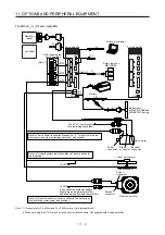
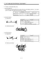
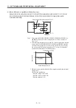
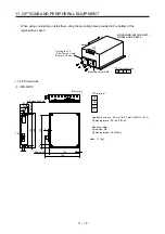
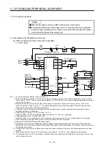
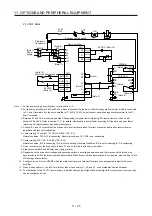
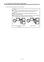
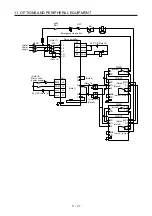
11.2.4 Connection of regenerative option
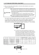
POINT
When the MR-RB50, MR-RB51, MR-RB5N, MR-RB3M-4, MR-RB3G-4, MR-
RB5G-4, MR-RB34-4, MR-RB54-4, MR-RB5K-4, or MR-RB6K-4 is used, a
cooling fan is required to cool it. The cooling fan should be prepared by the
customer.
For the sizes of wires used for wiring, refer to section 11.9.
The regenerative option generates heat of 100 °C higher than the ambient temperature. Fully consider heat
dissipation, installation position, used wires, etc. to place the option. For wiring, use flame-resistant wires or
make the wires flame-resistant and keep them away from the regenerative option. Use twisted wires with a
maximum length of 5 m for a connection with the servo amplifier.
Summary of Contents for MR-J4-100A(-RJ)
Page 19: ...10 MEMO ...
Page 75: ...1 FUNCTIONS AND CONFIGURATION 1 56 MEMO ...
Page 83: ...2 INSTALLATION 2 8 MEMO ...
Page 159: ...3 SIGNALS AND WIRING 3 76 MEMO ...
Page 203: ...4 STARTUP 4 44 MEMO ...
Page 351: ...7 SPECIAL ADJUSTMENT FUNCTIONS 7 40 MEMO ...
Page 365: ...8 TROUBLESHOOTING 8 14 MEMO ...
Page 387: ...9 DIMENSIONS 9 22 MEMO ...
Page 403: ...10 CHARACTERISTICS 10 16 MEMO ...
Page 553: ...12 ABSOLUTE POSITION DETECTION SYSTEM 12 30 MEMO ...
Page 567: ...13 USING STO FUNCTION 13 14 MEMO ...
Page 607: ...14 COMMUNICATION FUNCTION MITSUBISHI ELECTRIC GENERAL PURPOSE AC SERVO PROTOCOL 14 40 MEMO ...
Page 639: ...15 USING A LINEAR SERVO MOTOR 15 32 MEMO ...
Page 767: ...18 MR J4 03A6 RJ SERVO AMPLIFIER 18 84 MEMO ...
Page 856: ...APPENDIX App 41 ...
Page 905: ...MEMO ...


