


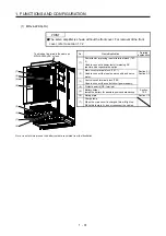
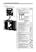

1. FUNCTIONS AND CONFIGURATION
1 - 17
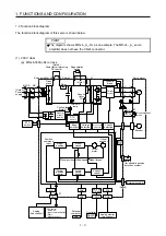
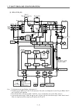
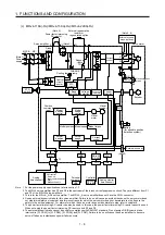
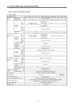
Model: MR-J4-_(-RJ)
10A1
20A1
40A1
Safety
performance
Standards certified by
CB (Note 8)
EN ISO 13849-1 Category 3 PL e, IEC 61508 SIL 3, EN 62061 SIL CL3, and EN 61800-5-2
Response performance
8 ms or less (STO input off
→
energy shut off)
Test pulse input (STO)
(Note 3)
Test pulse interval: 1 Hz to 25 Hz
Test pulse off time: Up to 1 ms
Mean time to dangerous
failure (MTTFd)
MTTFd
≥
100 [years] (314a)
Diagnostic coverage
(DC)
DC = Medium, 97.6 [%]
Average probability of
dangerous failures per
hour (PFH)
PFH = 6.4 × 10
-9
[1/h]
Compliance
with global
standards
CE marking
LVD: EN 61800-5-1
EMC: EN 61800-3
MD: EN ISO 13849-1, EN 61800-5-2, EN 62061
UL standard
UL 508C
Structure (IP rating)
Natural cooling, open (IP20)
Close mounting (Note 2)
Possible
Environment
Ambient
temperature
Operation 0
˚
C to 55
˚
C (non-freezing)
Storage -20
˚
C to 65
˚
C (non-freezing)
Ambient
humidity
Operation
5 %RH to 90 %RH (non-condensing)
Storage
Ambience
Indoors (no direct sunlight),
free from corrosive gas, flammable gas, oil mist, dust, and dirt
Altitude
2000 m or less above sea level (Note 9)
Vibration resistance
5.9 m/s
2
, at 10 Hz to 55 Hz (directions of X, Y and Z axes)
Mass
[kg]
0.8
1.0
Note 1. 0.5 A is the value applicable when all I/O signals are used. The current capacity can be decreased by reducing the number of
I/O points.
2. When closely mounting the servo amplifiers, operate them at the ambient temperature of 0
˚
C to 45
˚
C or at 75% or smaller
effective load ratio.
3. Test pulse is a signal which instantaneously turns off a signal to the servo amplifier at a constant period for external circuit to
self-diagnose.
4. 1 Mpulse/s or lower commands are supported in the initial setting. When inputting commands over 1 Mpulse/s and 4
Mpulses/s or lower, change the setting in [Pr. PA13].
5. For the compatible version for the fully closed loop system, refer to table 1.1. Check the software version of the servo amplifier
with MR Configurator2.
6. The MR-J4-_A servo amplifier is compatible only with the two-wire type.
The MR-J4-_A-RJ servo amplifier is compatible with the two-wire type, four-wire type, and A/B/Z-phase differential output
method. Refer to table 1.1 for details.
7. RS-485 communication is available with servo amplifiers manufactured in November 2014 or later.
8. The safety level depends on the setting value of [Pr. PF18 STO diagnosis error detection time] and whether STO input
diagnosis by TOFB output is performed or not. For details, refer to the Function column of [Pr. PF18] in section 5.2.6.
9. Follow the restrictions in section 2.6 when using this product at altitude exceeding 1000 m and up to 2000 m above sea level.
Summary of Contents for MR-J4-100A(-RJ)
Page 19: ...10 MEMO ...
Page 75: ...1 FUNCTIONS AND CONFIGURATION 1 56 MEMO ...
Page 83: ...2 INSTALLATION 2 8 MEMO ...
Page 159: ...3 SIGNALS AND WIRING 3 76 MEMO ...
Page 203: ...4 STARTUP 4 44 MEMO ...
Page 351: ...7 SPECIAL ADJUSTMENT FUNCTIONS 7 40 MEMO ...
Page 365: ...8 TROUBLESHOOTING 8 14 MEMO ...
Page 387: ...9 DIMENSIONS 9 22 MEMO ...
Page 403: ...10 CHARACTERISTICS 10 16 MEMO ...
Page 553: ...12 ABSOLUTE POSITION DETECTION SYSTEM 12 30 MEMO ...
Page 567: ...13 USING STO FUNCTION 13 14 MEMO ...
Page 607: ...14 COMMUNICATION FUNCTION MITSUBISHI ELECTRIC GENERAL PURPOSE AC SERVO PROTOCOL 14 40 MEMO ...
Page 639: ...15 USING A LINEAR SERVO MOTOR 15 32 MEMO ...
Page 767: ...18 MR J4 03A6 RJ SERVO AMPLIFIER 18 84 MEMO ...
Page 856: ...APPENDIX App 41 ...
Page 905: ...MEMO ...


