
3. SIGNALS AND WIRING
3 - 74
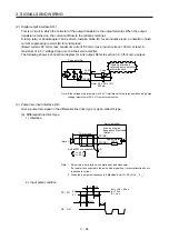
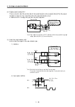
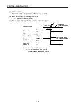
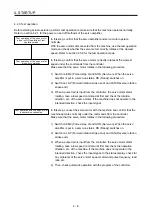
(c) Alarm occurrence
The operation status during an alarm is the same as section 3.8.
(d) Both main and control circuit power supplies off
It is the same as (1) (d) in this section.
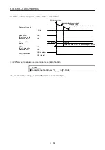
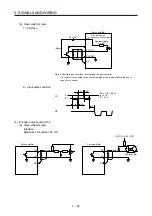
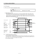
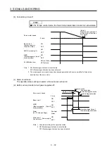
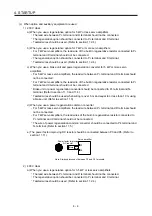
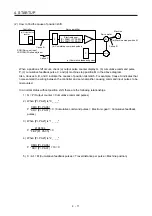
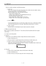
(e) Main circuit power supply off during control circuit power supply on
Dynamic brake
Dynamic brake
+ Electromagnetic brake
Electromagnetic brake
Operation delay time of
the electromagnetic brake
MBR
(Electromagnetic
brake interlock)
(Note 2)
Base circuit
Alarm
[AL. 10 Undervoltage]
No alarm
Alarm
Servo motor speed
Approx. 10 ms
(Note 1)
ON
OFF
ON
OFF
Main circuit
power supply
ON
OFF
0 r/min
Note 1. Variable according to the operation status.
2.
ON:
Electromagnetic
brake is not activated.
OFF: Electromagnetic brake has been activated.
Summary of Contents for MR-J4-100A(-RJ)
Page 19: ...10 MEMO ...
Page 75: ...1 FUNCTIONS AND CONFIGURATION 1 56 MEMO ...
Page 83: ...2 INSTALLATION 2 8 MEMO ...
Page 159: ...3 SIGNALS AND WIRING 3 76 MEMO ...
Page 203: ...4 STARTUP 4 44 MEMO ...
Page 351: ...7 SPECIAL ADJUSTMENT FUNCTIONS 7 40 MEMO ...
Page 365: ...8 TROUBLESHOOTING 8 14 MEMO ...
Page 387: ...9 DIMENSIONS 9 22 MEMO ...
Page 403: ...10 CHARACTERISTICS 10 16 MEMO ...
Page 553: ...12 ABSOLUTE POSITION DETECTION SYSTEM 12 30 MEMO ...
Page 567: ...13 USING STO FUNCTION 13 14 MEMO ...
Page 607: ...14 COMMUNICATION FUNCTION MITSUBISHI ELECTRIC GENERAL PURPOSE AC SERVO PROTOCOL 14 40 MEMO ...
Page 639: ...15 USING A LINEAR SERVO MOTOR 15 32 MEMO ...
Page 767: ...18 MR J4 03A6 RJ SERVO AMPLIFIER 18 84 MEMO ...
Page 856: ...APPENDIX App 41 ...
Page 905: ...MEMO ...


