


12. ABSOLUTE POSITION DETECTION SYSTEM
12 - 22
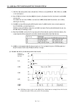
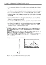
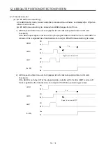
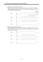
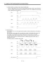
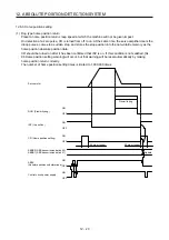
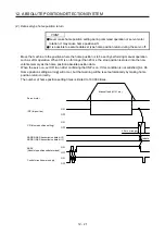
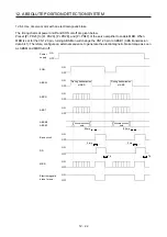
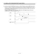
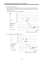
12.6.4 Use of servo motor with an electromagnetic brake
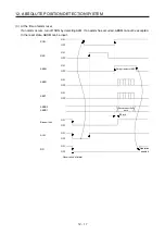
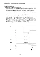
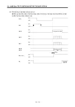
The timing charts at power on/off and SON on/off are given below.
Preset [Pr. PD23] to [Pr. PD26], [Pr. PD28], and [Pr. PD47] of the servo amplifier to enable MBR. When
MBR is set for the CN1-23 pin, turning ABSM on will change the CN1-23 pin to ABSB1 (ABS transmission
data bit 1). Therefore, configure an external sequence to generate the electromagnetic brake torque as soon
as ABSM and MBR turn off.
OFF
ON
OFF
ON
OFF
ON
OFF
ON
OFF
ON
OFF
ON
OFF
ON
OFF
ON
OFF
ON
95 ms
5 ms
Tb
95 ms
5 ms
Tb
Power
supply
SON
ABSM
ABSR
ABST
ABSB0
ABSB1
Base circuit
RD
MBR
Electromagnetic
brake torque
During transmission
of ABS
During transmission
of ABS
Absolute position
data
Absolute position
data
Summary of Contents for MR-J4-100A(-RJ)
Page 19: ...10 MEMO ...
Page 75: ...1 FUNCTIONS AND CONFIGURATION 1 56 MEMO ...
Page 83: ...2 INSTALLATION 2 8 MEMO ...
Page 159: ...3 SIGNALS AND WIRING 3 76 MEMO ...
Page 203: ...4 STARTUP 4 44 MEMO ...
Page 351: ...7 SPECIAL ADJUSTMENT FUNCTIONS 7 40 MEMO ...
Page 365: ...8 TROUBLESHOOTING 8 14 MEMO ...
Page 387: ...9 DIMENSIONS 9 22 MEMO ...
Page 403: ...10 CHARACTERISTICS 10 16 MEMO ...
Page 553: ...12 ABSOLUTE POSITION DETECTION SYSTEM 12 30 MEMO ...
Page 567: ...13 USING STO FUNCTION 13 14 MEMO ...
Page 607: ...14 COMMUNICATION FUNCTION MITSUBISHI ELECTRIC GENERAL PURPOSE AC SERVO PROTOCOL 14 40 MEMO ...
Page 639: ...15 USING A LINEAR SERVO MOTOR 15 32 MEMO ...
Page 767: ...18 MR J4 03A6 RJ SERVO AMPLIFIER 18 84 MEMO ...
Page 856: ...APPENDIX App 41 ...
Page 905: ...MEMO ...


