

3. SIGNALS AND WIRING
3 - 66
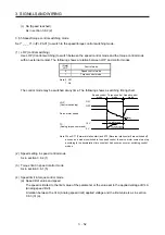
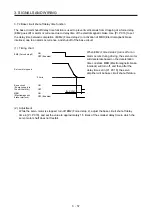
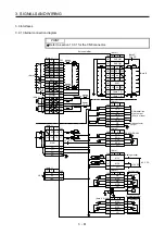
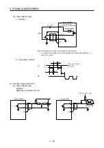
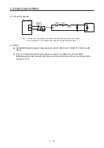
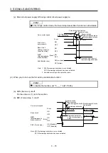
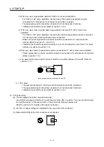
(b) Differential line driver type
1) Interface
Maximum output current: 35 mA
150
Ω
100
Ω
Am26LS32 or equivalent
Servo amplifier
LA
(LB, LZ)
LAR
(LBR, LZR)
SD
LG
High-speed photocoupler
Servo amplifier
LAR
(LBR, LZR)
SD
LA
(LB, LZ)
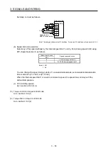
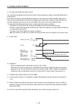
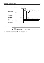
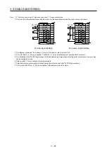
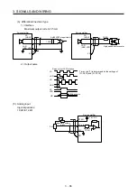
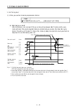
2) Output pulse
/2
T
400 s or more
Time cycle (T) is determined by the settings of
[Pr. PA15] and [Pr. PC19].
LA
LAR
LB
LBR
LZ
LZR
OP
Servo motor CCW rotation
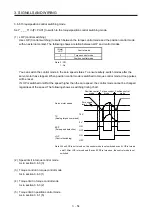
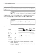
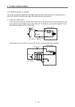
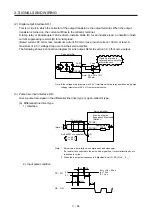
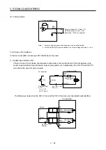
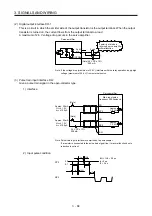
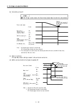
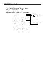
(5) Analog input
Input impedance
10 k
Ω
to 12 k
Ω
VC etc.
LG
P15R
SD
Approx.
10 k
Ω
+15 V DC
Upper limit setting
2 k
Ω
2 k
Ω
Servo amplifier
Summary of Contents for MR-J4-100A(-RJ)
Page 19: ...10 MEMO ...
Page 75: ...1 FUNCTIONS AND CONFIGURATION 1 56 MEMO ...
Page 83: ...2 INSTALLATION 2 8 MEMO ...
Page 159: ...3 SIGNALS AND WIRING 3 76 MEMO ...
Page 203: ...4 STARTUP 4 44 MEMO ...
Page 351: ...7 SPECIAL ADJUSTMENT FUNCTIONS 7 40 MEMO ...
Page 365: ...8 TROUBLESHOOTING 8 14 MEMO ...
Page 387: ...9 DIMENSIONS 9 22 MEMO ...
Page 403: ...10 CHARACTERISTICS 10 16 MEMO ...
Page 553: ...12 ABSOLUTE POSITION DETECTION SYSTEM 12 30 MEMO ...
Page 567: ...13 USING STO FUNCTION 13 14 MEMO ...
Page 607: ...14 COMMUNICATION FUNCTION MITSUBISHI ELECTRIC GENERAL PURPOSE AC SERVO PROTOCOL 14 40 MEMO ...
Page 639: ...15 USING A LINEAR SERVO MOTOR 15 32 MEMO ...
Page 767: ...18 MR J4 03A6 RJ SERVO AMPLIFIER 18 84 MEMO ...
Page 856: ...APPENDIX App 41 ...
Page 905: ...MEMO ...


