


11. OPTIONS AND PERIPHERAL EQUIPMENT
11 - 15
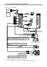
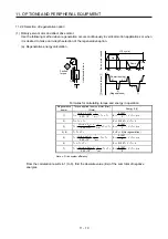
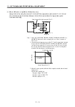
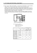
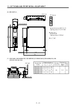
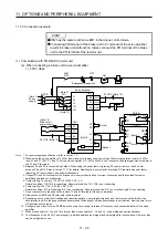
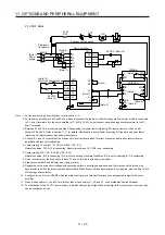
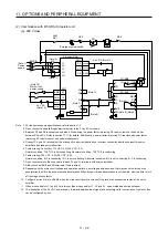
(2) MR-J4-500A4(-RJ)/MR-J4-700A(-RJ)/MR-J4-700A4(-RJ)
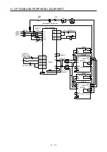
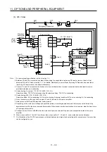
Always remove the wiring (across P+ to C) of the servo amplifier built-in regenerative resistor and fit the
regenerative option across P+ to C. G3 and G4 are thermal sensor's terminals. Between G3 and G4 is
opened when the regenerative option overheats abnormally.
Always remove the wiring (across P+ to C) of the
servo amplifier built-in regenerative resistor.
P+
C
G4
G3
C
P
Regenerative option
5 m or less
Servo amplifier
(Note 2)
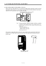
Cooling fan
(Note 1)
Note 1. When using the MR-RB51, MR-RB34-4, MR-RB54-4, MR-RB3U-4, or MR-RB5U-
4, forcibly cool it with a cooling fan (92 mm × 92 mm, minimum air flow: 1.0 m
3
).
2. Make up a sequence which will switch off the magnetic contactor when abnormal
heating occurs.
G3-G4 contact specifications
Maximum voltage: 120 V AC/DC
Maximum current: 0.5 A/4.8 V DC
Maximum capacity: 2.4 VA
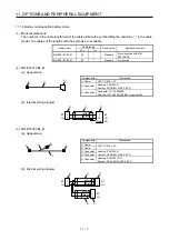
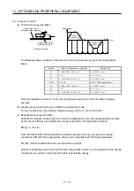
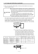
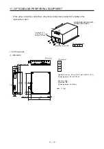
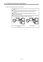
When using the regenerative option, remove the servo amplifier's built-in regenerative resistor wires
(across P+ to C), fit them back to back, and secure them to the frame with the accessory screw as
shown below.
Built-in regenerative resistor
lead terminal fixing screw
Accessory screw
Summary of Contents for MR-J4-100A(-RJ)
Page 19: ...10 MEMO ...
Page 75: ...1 FUNCTIONS AND CONFIGURATION 1 56 MEMO ...
Page 83: ...2 INSTALLATION 2 8 MEMO ...
Page 159: ...3 SIGNALS AND WIRING 3 76 MEMO ...
Page 203: ...4 STARTUP 4 44 MEMO ...
Page 351: ...7 SPECIAL ADJUSTMENT FUNCTIONS 7 40 MEMO ...
Page 365: ...8 TROUBLESHOOTING 8 14 MEMO ...
Page 387: ...9 DIMENSIONS 9 22 MEMO ...
Page 403: ...10 CHARACTERISTICS 10 16 MEMO ...
Page 553: ...12 ABSOLUTE POSITION DETECTION SYSTEM 12 30 MEMO ...
Page 567: ...13 USING STO FUNCTION 13 14 MEMO ...
Page 607: ...14 COMMUNICATION FUNCTION MITSUBISHI ELECTRIC GENERAL PURPOSE AC SERVO PROTOCOL 14 40 MEMO ...
Page 639: ...15 USING A LINEAR SERVO MOTOR 15 32 MEMO ...
Page 767: ...18 MR J4 03A6 RJ SERVO AMPLIFIER 18 84 MEMO ...
Page 856: ...APPENDIX App 41 ...
Page 905: ...MEMO ...


