


4. STARTUP
4 - 12
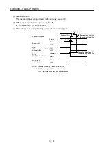
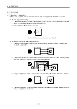
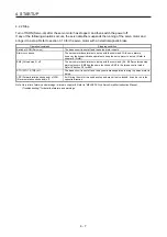
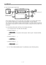
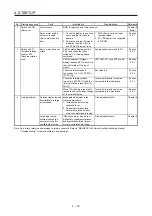
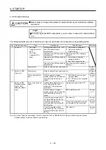
Check for a position mismatch in the following sequence.
1) When Q
≠
P
Noise entered the pulse train signal wiring between the controller and servo amplifier, causing
command input pulses to be miscounted. (Cause A)
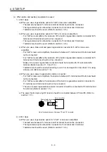
Make the following check or take the following measures.
Check how the shielding is done.
Change the open collector type to the differential line driver type.
Run wiring away from the power circuit.
Install a data line filter. (Refer to section 11.14 (2) (a).)
Change the [Pr. PA13 Command pulse input form] setting.
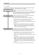
2) When P •
CMX
CDV
≠
C
During operation, SON (Servo-on), LSP (Forward rotation stroke end), or LSN (Reverse rotation
stroke end) was switched off; or CR (Clear) or RES (Reset) was switched on. (Cause C)
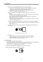
3) When C •
∆ℓ
≠
M
Mechanical slip occurred between the servo motor and machine. (Cause B)
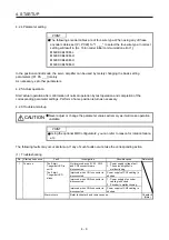
4.3 Startup in speed control mode
Make a startup in accordance with section 4.1. This section provides the methods specific to the speed
control mode.
4.3.1 Power on and off procedures
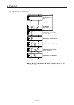
(1) Power-on
Switch power on in the following procedure. Always follow this procedure at power-on.
1) Switch off SON (Servo-on).
2) Make sure that ST1 (Forward rotation start) and ST2 (Reverse rotation start) are off.
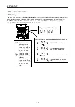
3) Switch on the main circuit power supply and control circuit power supply.
When main circuit power/control circuit power is switched on, the display shows "r (Servo motor
speed)", and in 2 s later, shows data.
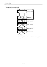
(2) Power-off
1) Switch off ST1 (Forward rotation start) and ST2 (Reverse rotation start).
2) Switch off SON (Servo-on).
3) Switch off the main circuit power supply and control circuit power supply.
Summary of Contents for MR-J4-100A(-RJ)
Page 19: ...10 MEMO ...
Page 75: ...1 FUNCTIONS AND CONFIGURATION 1 56 MEMO ...
Page 83: ...2 INSTALLATION 2 8 MEMO ...
Page 159: ...3 SIGNALS AND WIRING 3 76 MEMO ...
Page 203: ...4 STARTUP 4 44 MEMO ...
Page 351: ...7 SPECIAL ADJUSTMENT FUNCTIONS 7 40 MEMO ...
Page 365: ...8 TROUBLESHOOTING 8 14 MEMO ...
Page 387: ...9 DIMENSIONS 9 22 MEMO ...
Page 403: ...10 CHARACTERISTICS 10 16 MEMO ...
Page 553: ...12 ABSOLUTE POSITION DETECTION SYSTEM 12 30 MEMO ...
Page 567: ...13 USING STO FUNCTION 13 14 MEMO ...
Page 607: ...14 COMMUNICATION FUNCTION MITSUBISHI ELECTRIC GENERAL PURPOSE AC SERVO PROTOCOL 14 40 MEMO ...
Page 639: ...15 USING A LINEAR SERVO MOTOR 15 32 MEMO ...
Page 767: ...18 MR J4 03A6 RJ SERVO AMPLIFIER 18 84 MEMO ...
Page 856: ...APPENDIX App 41 ...
Page 905: ...MEMO ...


