


3. SIGNALS AND WIRING
3 - 62
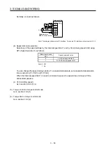
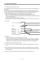
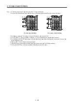
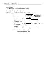
Note 1. P: Position control mode, S: Speed control mode, T: Torque control mode
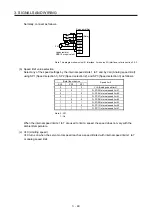
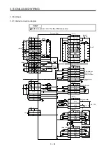
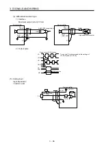
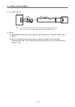
2. This is for the differential line driver pulse train input. For the open-collector pulse train input, connect as follows.
DOCOM
46
OPC
12
20
47
PP
10
PG
11
NP
35
NG
36
DICOM
DOCOM
PP2
37
NP2
38
24 V DC
DOCOM
46
OPC
12
20
47
PP
10
PG
11
NP
35
NG
36
DICOM
DOCOM
PP2
37
NP2
38
24 V DC
For sink input interface
For source input interface
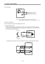
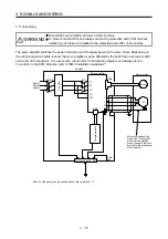
3. This diagram shows sink I/O interface. For source I/O interface, refer to section 3.9.3.
4. This is for MR-J4-_A_RJ servo amplifier. The MR-J4-_A_ servo amplifier does not have the CN2L connector.
5. The illustration of the 24 V DC power supply is divided between input signal and output signal for convenience. However, they
can be configured by one.
6. Refer to table 1.1 for connections of external encoders.
7. Output devices are not assigned by default. Assign the output devices with [Pr. PD47] as necessary.
8. This is used with MR-J4-_A_-RJ servo amplifiers with software version B3 or later.
Summary of Contents for MR-J4-100A(-RJ)
Page 19: ...10 MEMO ...
Page 75: ...1 FUNCTIONS AND CONFIGURATION 1 56 MEMO ...
Page 83: ...2 INSTALLATION 2 8 MEMO ...
Page 159: ...3 SIGNALS AND WIRING 3 76 MEMO ...
Page 203: ...4 STARTUP 4 44 MEMO ...
Page 351: ...7 SPECIAL ADJUSTMENT FUNCTIONS 7 40 MEMO ...
Page 365: ...8 TROUBLESHOOTING 8 14 MEMO ...
Page 387: ...9 DIMENSIONS 9 22 MEMO ...
Page 403: ...10 CHARACTERISTICS 10 16 MEMO ...
Page 553: ...12 ABSOLUTE POSITION DETECTION SYSTEM 12 30 MEMO ...
Page 567: ...13 USING STO FUNCTION 13 14 MEMO ...
Page 607: ...14 COMMUNICATION FUNCTION MITSUBISHI ELECTRIC GENERAL PURPOSE AC SERVO PROTOCOL 14 40 MEMO ...
Page 639: ...15 USING A LINEAR SERVO MOTOR 15 32 MEMO ...
Page 767: ...18 MR J4 03A6 RJ SERVO AMPLIFIER 18 84 MEMO ...
Page 856: ...APPENDIX App 41 ...
Page 905: ...MEMO ...


