


13. USING STO FUNCTION
13 - 9
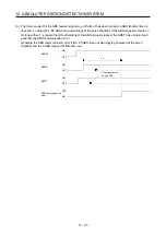
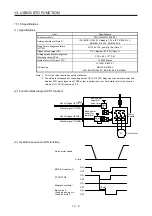
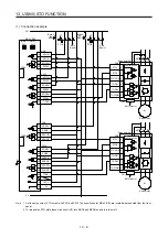
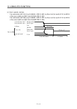
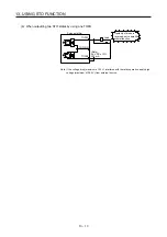
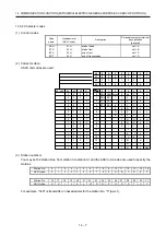
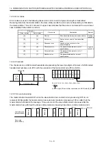
(2) Basic operation example
The switch status of STOA is input to SDI2A+ of MR-J3-D05, and then it will be input to STO1 and STO2
of the servo amplifier via SDO1A and SDO2A of MR-J3-D05.
The switch status of STOB is input to SDI2B+ of MR-J3-D05, and then it will be input to STO1 and STO2
of the servo amplifier via SDO1B and SDO2B of MR-J3-D05.
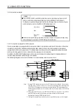
A-axis shutdown 1 and 2
B-axis shutdown 1 and 2
STO1, STO2
Stop
Operation
Energizing (close)
Shut-off (open)
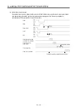
EM2 input
STO shut-off
Normal (close)
Shut-off (open)
0 r/min
Servo motor drivable
Servo motor speed
Servo amplifier
Shut off delay
STO status
Summary of Contents for MR-J4-100A(-RJ)
Page 19: ...10 MEMO ...
Page 75: ...1 FUNCTIONS AND CONFIGURATION 1 56 MEMO ...
Page 83: ...2 INSTALLATION 2 8 MEMO ...
Page 159: ...3 SIGNALS AND WIRING 3 76 MEMO ...
Page 203: ...4 STARTUP 4 44 MEMO ...
Page 351: ...7 SPECIAL ADJUSTMENT FUNCTIONS 7 40 MEMO ...
Page 365: ...8 TROUBLESHOOTING 8 14 MEMO ...
Page 387: ...9 DIMENSIONS 9 22 MEMO ...
Page 403: ...10 CHARACTERISTICS 10 16 MEMO ...
Page 553: ...12 ABSOLUTE POSITION DETECTION SYSTEM 12 30 MEMO ...
Page 567: ...13 USING STO FUNCTION 13 14 MEMO ...
Page 607: ...14 COMMUNICATION FUNCTION MITSUBISHI ELECTRIC GENERAL PURPOSE AC SERVO PROTOCOL 14 40 MEMO ...
Page 639: ...15 USING A LINEAR SERVO MOTOR 15 32 MEMO ...
Page 767: ...18 MR J4 03A6 RJ SERVO AMPLIFIER 18 84 MEMO ...
Page 856: ...APPENDIX App 41 ...
Page 905: ...MEMO ...


