

5. PARAMETERS
5 - 45
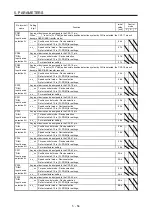
No./symbol/
name
Setting
digit
Function
Initial
value
[unit]
Control
mode
P S T
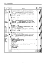
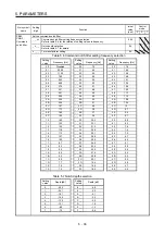
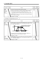
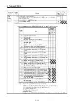
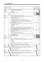
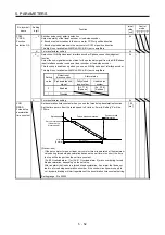
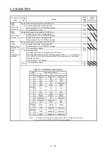
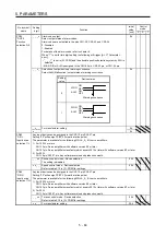
PC14
MOD1
Analog
monitor 1
output
Table 5.9 Analog monitor setting value (MR-J4-03A6(-RJ))
Setting
value
Item
_ _ 0 0 Servo motor speed (5 V ± 3 V/max. speed)
_ _ 0 1 Torque (5 V ± 3 V/max. torque) (Note 2)
_ _ 0 2 Servo motor speed (5 V + 3 V/max. speed)
_ _ 0 3 Torque (5 V + 3 V/max. torque) (Note 2)
_ _ 0 4 Current command (5 V ± 3 V/max. current command)
_ _ 0 5 Command pulse frequency (5 V ± 4 V/±4 Mpulses/s)
_ _ 0 6 Servo motor-side droop pulses (5 V ± 4 V/100 pulses)
(Note 1)
_ _ 0 7 Servo motor-side droop pulses (5 V ± 4 V/1000 pulses)
(Note 1)
_ _ 0 8 Servo motor-side droop pulses (5 V ± 4 V/10000
pulses) (Note 1)
_ _ 0 9 Servo motor-side droop pulses
(5 V ± 4 V/100000 pulses) (Note 1)
_ _ 0 A Feedback position (5 V ± 4 V/1 Mpulses) (Note 1)
_ _ 0 B Feedback position (5 V ± 4 V/10 Mpulses) (Note 1)
_ _ 0 C Feedback position (5 V ± 4 V/100 Mpulses) (Note 1)
_ _ 0 D Bus voltage (5 V + 4 V/100 V)
_ _ 0 E Speed command 2 (5 V ± 3 V/max. speed)
_ _ 1 7 Internal temperature of encoder (5 V ± 4 V/±128 °C)
Note 1. Encoder pulse unit
2. The larger value of [Pr. PA11] or [Pr. PA12] will be the maximum torque.
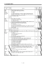
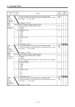
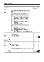
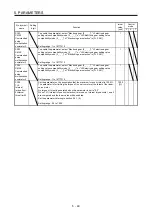
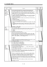
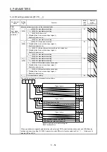
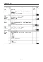
PC15
MOD2
Analog
monitor 2
output
_ _ x x Analog monitor 2 output selection
Select a signal to output to MO2 (Analog monitor 2). Refer to app. 7.3 for detection
point of output selection.
Refer to [Pr. PC14] for settings.
01h
_ x _ _ For manufacturer setting
0h
x _ _ _
0h
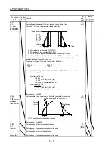
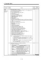
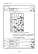
PC16
MBR
Electromagnetic
brake sequence
output
Set the delay time between MBR (Electromagnetic brake interlock) and the base
drive circuit is shut-off.
Setting range: 0 to 1000
0
[ms]
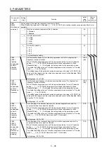
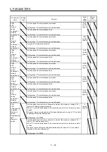
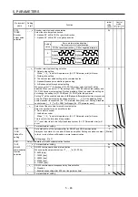
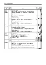
PC17
ZSP
Zero speed
Set the output range of ZSP (Zero speed detection).
ZSP (Zero speed detection) has hysteresis of 20 r/min or 20 mm/s.
Setting range: 0 to 10000
50
[r/min]/
[mm/s]
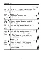
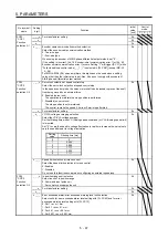
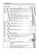
PC18
*BPS
Alarm history
clear
_ _ _ x Alarm history clear selection
Clear the alarm history.
0: Disabled
1: Enabled
When "Enabled" is set, the alarm history will be cleared at the next power-on. Once
the alarm history is cleared, the setting becomes disabled automatically.
0h
_ _ x _ For manufacturer setting
0h
_ x _ _
0h
x _ _ _
0h
Summary of Contents for MR-J4-100A(-RJ)
Page 19: ...10 MEMO ...
Page 75: ...1 FUNCTIONS AND CONFIGURATION 1 56 MEMO ...
Page 83: ...2 INSTALLATION 2 8 MEMO ...
Page 159: ...3 SIGNALS AND WIRING 3 76 MEMO ...
Page 203: ...4 STARTUP 4 44 MEMO ...
Page 351: ...7 SPECIAL ADJUSTMENT FUNCTIONS 7 40 MEMO ...
Page 365: ...8 TROUBLESHOOTING 8 14 MEMO ...
Page 387: ...9 DIMENSIONS 9 22 MEMO ...
Page 403: ...10 CHARACTERISTICS 10 16 MEMO ...
Page 553: ...12 ABSOLUTE POSITION DETECTION SYSTEM 12 30 MEMO ...
Page 567: ...13 USING STO FUNCTION 13 14 MEMO ...
Page 607: ...14 COMMUNICATION FUNCTION MITSUBISHI ELECTRIC GENERAL PURPOSE AC SERVO PROTOCOL 14 40 MEMO ...
Page 639: ...15 USING A LINEAR SERVO MOTOR 15 32 MEMO ...
Page 767: ...18 MR J4 03A6 RJ SERVO AMPLIFIER 18 84 MEMO ...
Page 856: ...APPENDIX App 41 ...
Page 905: ...MEMO ...


