

18. MR-J4-03A6(-RJ) SERVO AMPLIFIER
18 - 2
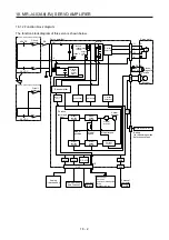
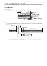
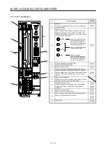
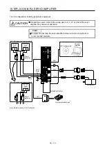
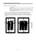
18.1.2 Function block diagram
The function block diagram of this servo is shown below.
Model
position
Current
control
Actual
position
control
Actual
speed
control
Virtual
motor
Virtual
encoder
Position
command
input
Model
speed
Model torque
Model
position
control
Model
speed
control
CN3
Analog monitor
(two channel)
I/F
USB
A/D
D/A
USB
Personal
computer
Analog
(two channel)
DI/O control
Servo-on
Input command pulse.
Start
Malfunction, etc
CN1
Current
detection
Overvoltage
Overcurrent
RS-422
Controller
RS-422
Current
detector
Regene
-rative
TR
Control
circuit
power
supply
Servo amplifier
+
+
CHARGE
lamp
RA
PM
0
Built-in
regenerative
resistor
Inverter
CNP1
Circuit
protector
48 V DC
24 V DC
Circuit
protector
24 V DC
24 V DC main circuit power supply
24
U
V
W
U
V
W
Electro-
magnetic
brake
B
RA
24 V DC
B1
B2
Encoder
Servo motor
M
CNP1
CN2
CN4
Base amplifier
Regenerative
brake
Step-
down
circuit
MR-BAT6V1SET-A
Battery
(for absolute position
detection system)
E
48 V DC main circuit power supply
Summary of Contents for MR-J4-100A(-RJ)
Page 19: ...10 MEMO ...
Page 75: ...1 FUNCTIONS AND CONFIGURATION 1 56 MEMO ...
Page 83: ...2 INSTALLATION 2 8 MEMO ...
Page 159: ...3 SIGNALS AND WIRING 3 76 MEMO ...
Page 203: ...4 STARTUP 4 44 MEMO ...
Page 351: ...7 SPECIAL ADJUSTMENT FUNCTIONS 7 40 MEMO ...
Page 365: ...8 TROUBLESHOOTING 8 14 MEMO ...
Page 387: ...9 DIMENSIONS 9 22 MEMO ...
Page 403: ...10 CHARACTERISTICS 10 16 MEMO ...
Page 553: ...12 ABSOLUTE POSITION DETECTION SYSTEM 12 30 MEMO ...
Page 567: ...13 USING STO FUNCTION 13 14 MEMO ...
Page 607: ...14 COMMUNICATION FUNCTION MITSUBISHI ELECTRIC GENERAL PURPOSE AC SERVO PROTOCOL 14 40 MEMO ...
Page 639: ...15 USING A LINEAR SERVO MOTOR 15 32 MEMO ...
Page 767: ...18 MR J4 03A6 RJ SERVO AMPLIFIER 18 84 MEMO ...
Page 856: ...APPENDIX App 41 ...
Page 905: ...MEMO ...


