


7. SPECIAL ADJUSTMENT FUNCTIONS
7 - 18
7.2.3 Parameter
When using the gain switching function, always select "Manual mode (_ _ _ 3)" of "Gain adjustment mode
selection" in [Pr. PA08 Auto tuning mode]. The gain switching function cannot be used in the auto tuning
mode.
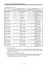
(1) Parameter for setting gain switching condition
Parameter Symbol
Name
Unit
Description
PB26
CDP
Gain switching function
Select a switching condition.
PB27
CDL
Gain switching condition
[kpulse/s]
/[pulse]
/[r/min]
Set a switching condition values.
PB28
CDT
Gain switching time constant
[ms]
Set the filter time constant for a gain change at switching.
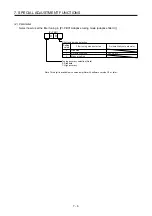
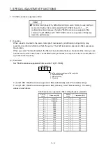
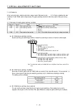
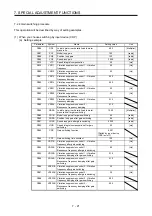
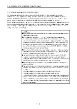
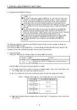
(a) [Pr. PB26 Gain switching function]
Used to set the gain switching condition. Select the switching condition in the first to third digits.
Gain switching selection
0: Disabled
1: Input device (gain switching (CDP))
2: Command frequency
3: Droop pulses
4: Servo motor speed/linear servo motor speed
0
Gain switching condition
0: Gain after switching is enabled with gain switching condition or more
1: Gain after switching is enabled with gain switching condition or less
[Pr. PB26]
Gain switching time constant disabling condition selection (Note)
0: Switching time constant enabled
1: Switching time constant disabled
2: Return time constant disabled
Note. This parameter setting is available with servo amplifiers with software version B4 or
later.
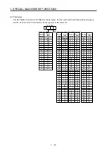
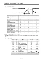
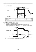
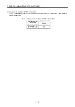
(b) [Pr. PB27 Gain switching condition]
Set a level to switch gains with [Pr. PB27] after you select "Command frequency", "Droop pulses", or
"Servo motor speed" with the gain switching selection in [Pr. PB26 Gain switching function].
The setting unit is as follows.
Gain switching condition
Unit
Command frequency
[kpulse/s]
Droop pulses
[pulse]
Servo motor speed
[r/min]
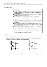
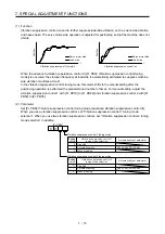
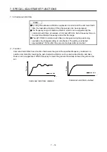
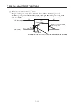
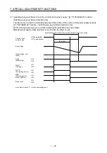
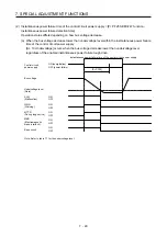
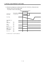
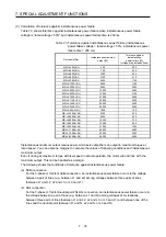
(c) [Pr. PB28 Gain switching time constant]
You can set the primary delay filter to each gain at gain switching. This parameter is used to
suppress shock given to the machine if the gain difference is large at gain switching, for example.
Summary of Contents for MR-J4-100A(-RJ)
Page 19: ...10 MEMO ...
Page 75: ...1 FUNCTIONS AND CONFIGURATION 1 56 MEMO ...
Page 83: ...2 INSTALLATION 2 8 MEMO ...
Page 159: ...3 SIGNALS AND WIRING 3 76 MEMO ...
Page 203: ...4 STARTUP 4 44 MEMO ...
Page 351: ...7 SPECIAL ADJUSTMENT FUNCTIONS 7 40 MEMO ...
Page 365: ...8 TROUBLESHOOTING 8 14 MEMO ...
Page 387: ...9 DIMENSIONS 9 22 MEMO ...
Page 403: ...10 CHARACTERISTICS 10 16 MEMO ...
Page 553: ...12 ABSOLUTE POSITION DETECTION SYSTEM 12 30 MEMO ...
Page 567: ...13 USING STO FUNCTION 13 14 MEMO ...
Page 607: ...14 COMMUNICATION FUNCTION MITSUBISHI ELECTRIC GENERAL PURPOSE AC SERVO PROTOCOL 14 40 MEMO ...
Page 639: ...15 USING A LINEAR SERVO MOTOR 15 32 MEMO ...
Page 767: ...18 MR J4 03A6 RJ SERVO AMPLIFIER 18 84 MEMO ...
Page 856: ...APPENDIX App 41 ...
Page 905: ...MEMO ...


