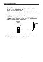
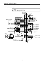
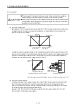

3. SIGNALS AND WIRING
3 - 29
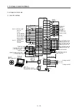
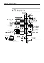
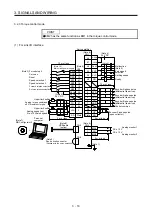
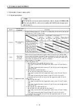
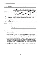
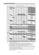
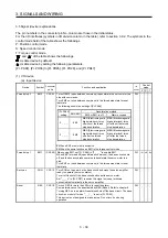
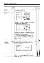
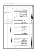
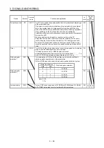
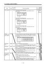
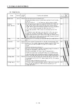
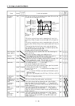
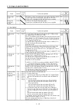
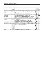
Pin No.
(Note 1)
I/O
(Note 2) I/O signals in control modes
Related parameter
P P/S S S/T T T/P
1
P15R P15R P15R P15R P15R P15R
2 I -/VC
VC
VC/VLA
VLA
VLA/-
3 LG LG LG LG LG LG
4 O LA LA LA LA LA LA
5
O LAR LAR LAR LAR LAR LAR
6 O LB LB LB LB LB LB
7
O LBR LBR LBR LBR LBR LBR
8 O LZ LZ LZ LZ LZ LZ
9
O LZR LZR LZR LZR LZR LZR
10 I PP
PP/-
(Note 6)
(Note 6)
(Note 6)
-/PP
PD43/PD44 (Note 5)
11 I PG
PG/- -/PG
12 OPC
OPC/-
-/OPC
13
O
(Note 4)
(Note 4)
(Note 4)
(Note 4)
(Note 4)
(Note 4)
PD47 (Note 5)
14
O
(Note 4)
(Note 4)
(Note 4)
(Note 4)
(Note 4)
(Note 4)
PD47 (Note 5)
15
I SON SON SON SON SON SON
PD03/PD04
16
I
-/SP2 SP2
SP2/SP2
SP2 SP2/-
PD05/PD06
17 I PC
PC/ST1
ST1
ST1/RS2 RS2 RS2/PC
PD07/PD08
18 I TL
TL/ST2
ST2
ST2/RS1
RS1
RS1/TL
PD09/PD10
19
I RES RES RES RES RES RES
PD11/PD12
20
DICOM DICOM DICOM DICOM DICOM DICOM
21
DICOM DICOM DICOM DICOM DICOM DICOM
22 O INP
INP/SA
SA
SA/- -/INP
PD23
23 O ZSP
ZSP
ZSP
ZSP ZSP ZSP
PD24
24 O INP
INP/SA
SA
SA/- -/INP
PD25
25
O
TLC
TLC
TLC TLC/VLC VLC VLC/TLC
PD26
26
27 I TLA
(Note 3)
TLA
(Note 3)
TLA
(Note 3)
TLA/TC
TC TC/TLA
28 LG LG LG LG LG LG
29
30 LG LG LG LG LG LG
31
32
33 O OP OP OP OP OP OP
34 LG LG LG LG LG LG
35
I
NP
NP/-
(Note 6)
(Note 6)
(Note 6)
-/NP
PD45/PD46 (Note 5)
36 I NG
NG/- -/NG
(Note 8) 37
I
PP2
PP2/-
(Note 7)
(Note 7)
(Note 7)
-/PP2
PD43/PD44 (Note 5)
(Note 8) 38
I
NP2
NP2/-
(Note 7)
(Note 7) (Note
7) -/NP2
PD45/PD46 (Note 5)
39
40
41 I CR
CR/SP1
SP1
SP1/SP1 SP1 SP1/CR
PD13/PD14
42
I EM2 EM2 EM2 EM2 EM2 EM2
43 I LSP
LSP
LSP
LSP/- -/LSP
PD17/PD18
44 I LSN
LSN
LSN
LSN/-
-/LSN
PD19/PD20
45
I LOP LOP LOP LOP LOP LOP
PD21/PD22
46
DOCOM
DOCOM
DOCOM
DOCOM DOCOM DOCOM
47
DOCOM
DOCOM
DOCOM
DOCOM DOCOM DOCOM
48 O ALM ALM ALM ALM ALM ALM
49 O RD RD RD RD RD RD
PD28
50
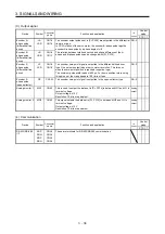
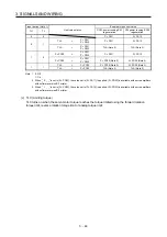
Note 1. I: Input signal, O: Output signal
2. P: Position control mode, S: Speed control mode, T: Torque control mode, P/S: Position/speed control change
mode, S/T: Speed/torque control change mode, T/P: Torque/position control change mode
3. TLA will be available when TL (External torque limit selection) is enabled with [Pr. PD03] to [Pr. PD22].
4. Output devices are not assigned by default. Assign the output devices with [Pr. PD47] as necessary.
5. This is used with MR-J4-_A_-RJ servo amplifiers with software version B3 or later.
6. This is available as an input device of sink interface. Input devices are not assigned by default. Assign the input
devices with [Pr. PD43] to [Pr. PD46] as necessary. of 24 V DC to CN1-12 pin. Also, this is available
with servo amplifiers with software version B3 or later.
7. This is available as an input device of source interface. Input devices are not assigned by default. Assign the
input devices with [Pr. PD43] to [Pr. PD46] as necessary.
8. These pins are available for MR-J4-_A_(-RJ) servo amplifiers manufactured in January 2015 or later with
software version B7 or later.
Summary of Contents for MR-J4-100A(-RJ)
Page 19: ...10 MEMO ...
Page 75: ...1 FUNCTIONS AND CONFIGURATION 1 56 MEMO ...
Page 83: ...2 INSTALLATION 2 8 MEMO ...
Page 159: ...3 SIGNALS AND WIRING 3 76 MEMO ...
Page 203: ...4 STARTUP 4 44 MEMO ...
Page 351: ...7 SPECIAL ADJUSTMENT FUNCTIONS 7 40 MEMO ...
Page 365: ...8 TROUBLESHOOTING 8 14 MEMO ...
Page 387: ...9 DIMENSIONS 9 22 MEMO ...
Page 403: ...10 CHARACTERISTICS 10 16 MEMO ...
Page 553: ...12 ABSOLUTE POSITION DETECTION SYSTEM 12 30 MEMO ...
Page 567: ...13 USING STO FUNCTION 13 14 MEMO ...
Page 607: ...14 COMMUNICATION FUNCTION MITSUBISHI ELECTRIC GENERAL PURPOSE AC SERVO PROTOCOL 14 40 MEMO ...
Page 639: ...15 USING A LINEAR SERVO MOTOR 15 32 MEMO ...
Page 767: ...18 MR J4 03A6 RJ SERVO AMPLIFIER 18 84 MEMO ...
Page 856: ...APPENDIX App 41 ...
Page 905: ...MEMO ...


