
16. USING A DIRECT DRIVE MOTOR
16 - 9
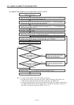
(2) Operation at the magnetic pole detection
WARNING
Note that the magnetic pole detection automatically starts simultaneously with the
turning-on of the servo-on command.
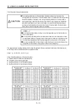
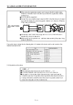
CAUTION
If the magnetic pole detection is not executed properly, the direct drive motor may
operates unexpectedly.
POINT
Establish the machine configuration to use LSP (Forward rotation stroke end)
and LSN (Reverse rotation stroke end). The machine may be damaged due to a
collision without LSP and LSN.
Assign LSP and LSN and perform the magnetic pole detection also in the torque
control mode.
At the magnetic pole detection, whether the motor rotates in the forward or
reverse direction is unpredictable.
Depending on the setting value of [Pr. PL09 Magnetic pole detection voltage
level], an overload, overcurrent, magnetic pole detection alarm, or others may
occur.
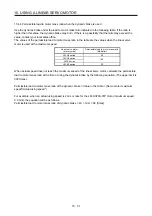
After the magnetic pole detection, check the positioning accuracy with the test
operation (positioning operation function) of MR Configurator2.
The accuracy of the magnetic pole detection improves with no load.
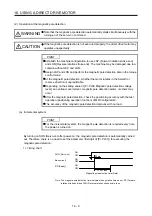
(a) Incremental system
POINT
For the incremental system, the magnetic pole detection is required every time
the power is turned on.
By turning on SON (Servo-on) after power-on, the magnetic pole detection is automatically carried
out. Therefore, there is no need to set the parameter (first digit of [Pr. PL01]) for executing the
magnetic pole detection.
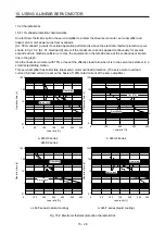
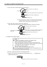
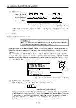
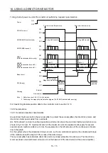
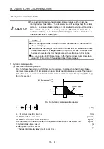
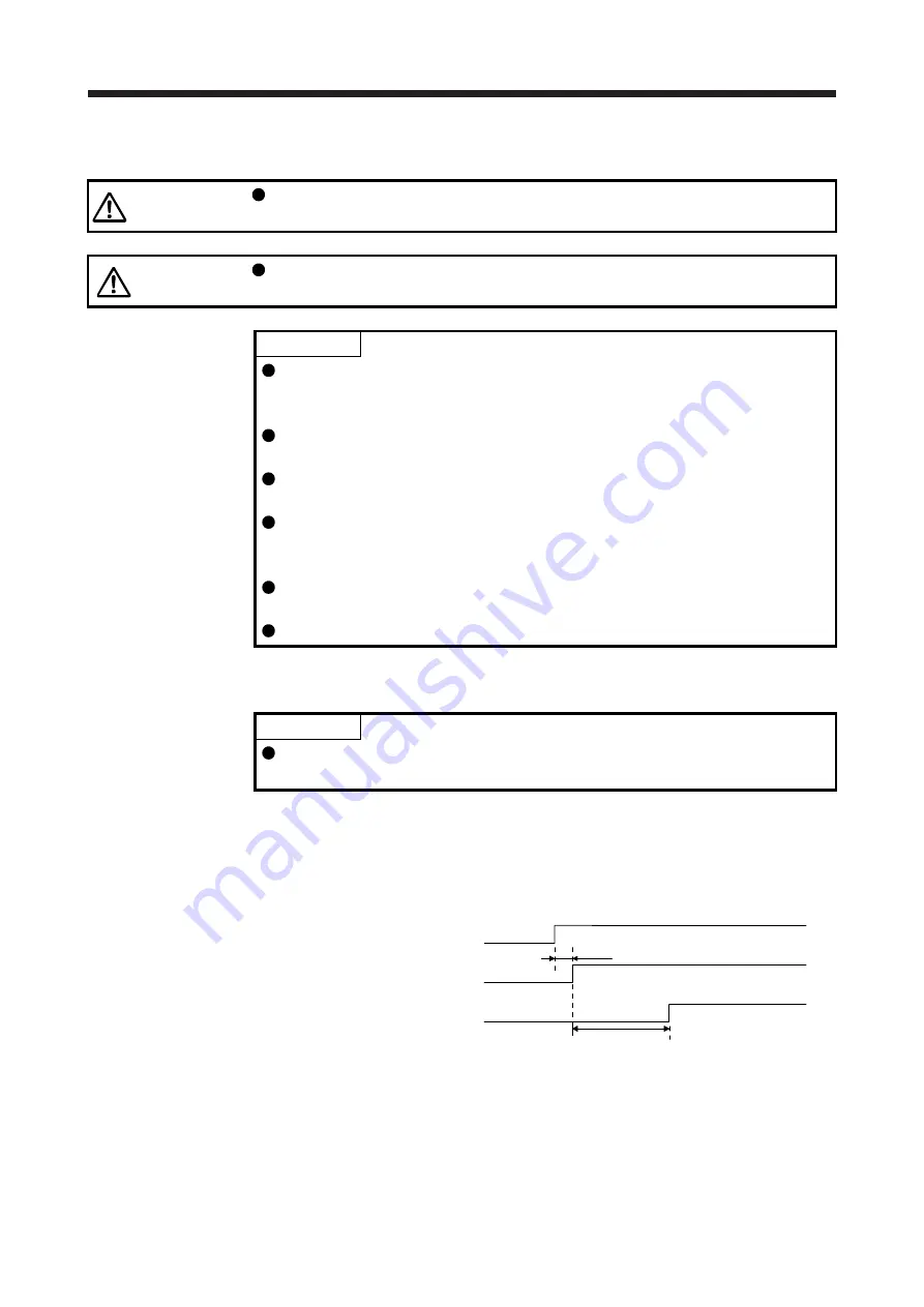
1) Timing chart
15 s or less
ON
OFF
ON
OFF
ON
OFF
95 ms
SON (Servo-on)
Base circuit
RD (Ready)
Magnetic pole detection time (Note)
Note. The magnetic pole detection time indicates the operation time when LSP (Forward
rotation stroke end) and LSN (Reverse rotation stroke end) are on.
Summary of Contents for MR-J4-100A(-RJ)
Page 19: ...10 MEMO ...
Page 75: ...1 FUNCTIONS AND CONFIGURATION 1 56 MEMO ...
Page 83: ...2 INSTALLATION 2 8 MEMO ...
Page 159: ...3 SIGNALS AND WIRING 3 76 MEMO ...
Page 203: ...4 STARTUP 4 44 MEMO ...
Page 351: ...7 SPECIAL ADJUSTMENT FUNCTIONS 7 40 MEMO ...
Page 365: ...8 TROUBLESHOOTING 8 14 MEMO ...
Page 387: ...9 DIMENSIONS 9 22 MEMO ...
Page 403: ...10 CHARACTERISTICS 10 16 MEMO ...
Page 553: ...12 ABSOLUTE POSITION DETECTION SYSTEM 12 30 MEMO ...
Page 567: ...13 USING STO FUNCTION 13 14 MEMO ...
Page 607: ...14 COMMUNICATION FUNCTION MITSUBISHI ELECTRIC GENERAL PURPOSE AC SERVO PROTOCOL 14 40 MEMO ...
Page 639: ...15 USING A LINEAR SERVO MOTOR 15 32 MEMO ...
Page 767: ...18 MR J4 03A6 RJ SERVO AMPLIFIER 18 84 MEMO ...
Page 856: ...APPENDIX App 41 ...
Page 905: ...MEMO ...


