A - 4
CAUTION
When fumigants that contain halogen materials, such as fluorine, chlorine, bromine, and iodine, are used
for disinfecting and protecting wooden packaging from insects, they cause a malfunction when entering
our products. Please take necessary precautions to ensure that remaining materials from fumigant do not
enter our products, or treat packaging with methods other than fumigation, such as heat treatment.
Additionally, disinfect and protect wood from insects before packing the products.
To prevent a fire or injury in case of an earthquake or other natural disasters, securely install, mount, and
wire the servo motor in accordance with the Instruction Manual.
(2) Wiring
CAUTION
Wire the equipment correctly and securely. Otherwise, the servo motor may operate unexpectedly.
Make sure to connect the cables and connectors by using the fixing screws and the locking mechanism.
Otherwise, the cables and connectors may be disconnected during operation.
Do not install a power capacitor, surge killer, or radio noise filter (optional FR-BIF(-H)) on the servo
amplifier output side.
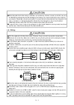
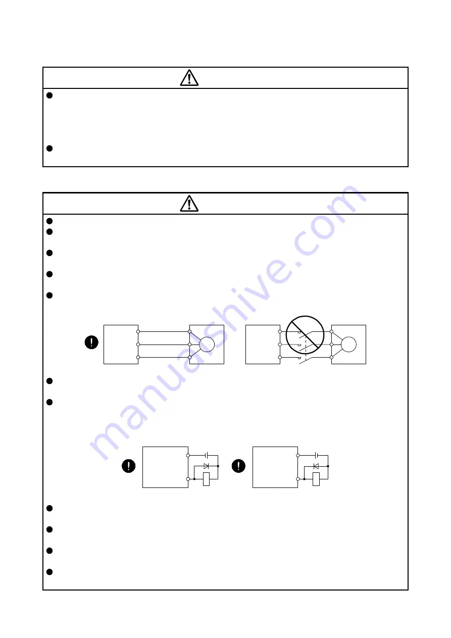
To avoid a malfunction, connect the wires to the correct phase terminals (U/V/W) of the servo amplifier
and servo motor.
Connect the servo amplifier power output (U/V/W) to the servo motor power input (U/V/W) directly. Do
not connect a magnetic contactor and others between them. Otherwise, it may cause a malfunction.
U
Servo motor
M
V
W
U
V
W
U
M
V
W
U
V
W
Servo amplifier
Servo motor
Servo amplifier
The connection diagrams in this Instruction Manual are shown for sink interfaces, unless stated
otherwise.
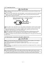
The surge absorbing diode installed to the DC relay for control output should be fitted in the specified
direction. Otherwise, the converter unit and the drive unit will malfunction and will not output signals,
disabling the emergency stop and other protective circuits.
DOCOM
(DOCOMD)
Control output
signal
Servo amplifier
or MR-D01
RA
For sink output interface
24 V DC
DOCOM
(DOCOMD)
Control output
signal
24 V DC
Servo amplifier
or MR-D01
RA
For source output interface
When the wires are not tightened enough to the terminal block, the wires or terminal block may generate
heat because of the poor contact. Be sure to tighten the wires with specified torque.
Connecting a servo motor of the wrong axis to U, V, W, or CN2 of the servo amplifier may cause a
malfunction.
Configure a circuit to turn off EM2 or EM1 when the main circuit power supply is turned off to prevent an
unexpected restart of the servo amplifier.
To prevent malfunction, avoid bundling power lines (input/output) and signal cables together or running
them in parallel to each other. Separate the power lines from the signal cables.
Summary of Contents for MR-J4-100A(-RJ)
Page 19: ...10 MEMO ...
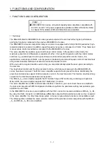
Page 75: ...1 FUNCTIONS AND CONFIGURATION 1 56 MEMO ...
Page 83: ...2 INSTALLATION 2 8 MEMO ...
Page 159: ...3 SIGNALS AND WIRING 3 76 MEMO ...
Page 203: ...4 STARTUP 4 44 MEMO ...
Page 351: ...7 SPECIAL ADJUSTMENT FUNCTIONS 7 40 MEMO ...
Page 365: ...8 TROUBLESHOOTING 8 14 MEMO ...
Page 387: ...9 DIMENSIONS 9 22 MEMO ...
Page 403: ...10 CHARACTERISTICS 10 16 MEMO ...
Page 553: ...12 ABSOLUTE POSITION DETECTION SYSTEM 12 30 MEMO ...
Page 567: ...13 USING STO FUNCTION 13 14 MEMO ...
Page 607: ...14 COMMUNICATION FUNCTION MITSUBISHI ELECTRIC GENERAL PURPOSE AC SERVO PROTOCOL 14 40 MEMO ...
Page 639: ...15 USING A LINEAR SERVO MOTOR 15 32 MEMO ...
Page 767: ...18 MR J4 03A6 RJ SERVO AMPLIFIER 18 84 MEMO ...
Page 856: ...APPENDIX App 41 ...
Page 905: ...MEMO ...


