
7. SPECIAL ADJUSTMENT FUNCTIONS
7 - 39
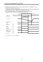
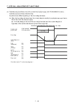
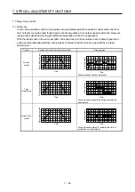
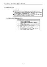
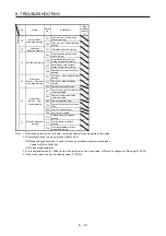
(2) Adjustment procedure
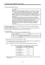
POINT
In the super trace control, droop pulses are near 0 during the servo motor
control. Thus, the normal INP (In-position) may always be turned on. Be sure to
set "INP (In-position) on condition selection" in [Pr. PD31] to " _ 1 _ _".
When you use the super trace control, it is recommended that the acceleration
time constant up to the rated speed be set to 1 s or more.
The following shows the adjustment procedure.
Step Operation
1
Execute the gain adjustment with one-touch tuning, auto tuning,
etc. Refer to chapter 6 for details.
2
Change the setting of auto tuning mode to the manual mode ([Pr.
PA08]: _ _ _ 3).
3
Change the setting of feed forward gain ([Pr. PB04]), and adjust
that droop pulses will be 0 at a constant speed.
4
Set the setting of INP (In-position) on condition selection ([Pr.
PD31]) to " _ 1 _ _".
5
Enable the super trace control. ([Pr. PA22]: _ _ 2 _)
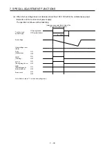
6
Change the setting of model loop gain ([Pr. PB07]), and adjust
droop pulses during acceleration/deceleration.
Summary of Contents for MR-J4-100A(-RJ)
Page 19: ...10 MEMO ...
Page 75: ...1 FUNCTIONS AND CONFIGURATION 1 56 MEMO ...
Page 83: ...2 INSTALLATION 2 8 MEMO ...
Page 159: ...3 SIGNALS AND WIRING 3 76 MEMO ...
Page 203: ...4 STARTUP 4 44 MEMO ...
Page 351: ...7 SPECIAL ADJUSTMENT FUNCTIONS 7 40 MEMO ...
Page 365: ...8 TROUBLESHOOTING 8 14 MEMO ...
Page 387: ...9 DIMENSIONS 9 22 MEMO ...
Page 403: ...10 CHARACTERISTICS 10 16 MEMO ...
Page 553: ...12 ABSOLUTE POSITION DETECTION SYSTEM 12 30 MEMO ...
Page 567: ...13 USING STO FUNCTION 13 14 MEMO ...
Page 607: ...14 COMMUNICATION FUNCTION MITSUBISHI ELECTRIC GENERAL PURPOSE AC SERVO PROTOCOL 14 40 MEMO ...
Page 639: ...15 USING A LINEAR SERVO MOTOR 15 32 MEMO ...
Page 767: ...18 MR J4 03A6 RJ SERVO AMPLIFIER 18 84 MEMO ...
Page 856: ...APPENDIX App 41 ...
Page 905: ...MEMO ...


