


4. STARTUP
4 - 29
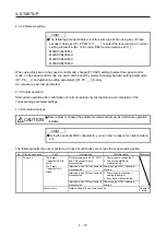
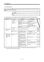
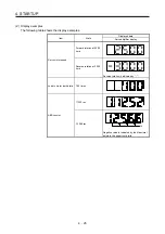
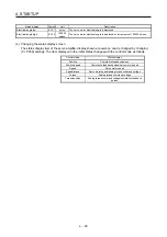
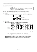
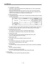
Status display
Symbol
Unit
Description
Electrical angle low
ECY1
pulse
The servo motor electrical angle is displayed.
Electrical angle high
ECY2
100000
pulses
The servo motor electrical angle is displayed by increments of 100000 pulses.
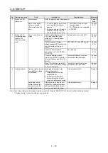
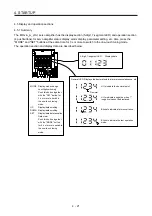
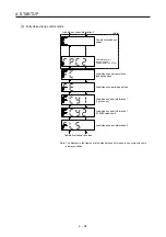
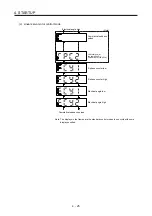
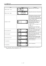
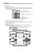
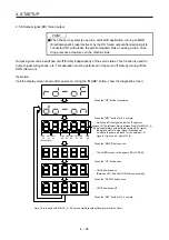
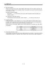
(4) Changing the status display screen
The status display item of the servo amplifier display shown at power-on can be changed by changing
[Pr. PC36] settings. The item displayed in the initial status changes with the control mode as follows.
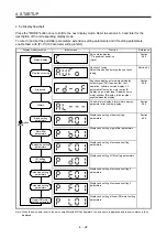
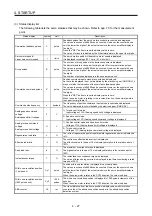
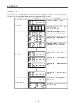
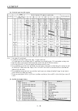
Control mode
Status display
Position
Cumulative feedback pulses
Position/speed
Cumulative feedback pulses/servo motor speed
Speed
Servo motor speed
Speed/torque
Servo motor speed/analog torque command voltage
Torque
Analog torque command voltage
Torque/position
Analog torque command voltage/cumulative feedback
pulses
Summary of Contents for MR-J4-100A(-RJ)
Page 19: ...10 MEMO ...
Page 75: ...1 FUNCTIONS AND CONFIGURATION 1 56 MEMO ...
Page 83: ...2 INSTALLATION 2 8 MEMO ...
Page 159: ...3 SIGNALS AND WIRING 3 76 MEMO ...
Page 203: ...4 STARTUP 4 44 MEMO ...
Page 351: ...7 SPECIAL ADJUSTMENT FUNCTIONS 7 40 MEMO ...
Page 365: ...8 TROUBLESHOOTING 8 14 MEMO ...
Page 387: ...9 DIMENSIONS 9 22 MEMO ...
Page 403: ...10 CHARACTERISTICS 10 16 MEMO ...
Page 553: ...12 ABSOLUTE POSITION DETECTION SYSTEM 12 30 MEMO ...
Page 567: ...13 USING STO FUNCTION 13 14 MEMO ...
Page 607: ...14 COMMUNICATION FUNCTION MITSUBISHI ELECTRIC GENERAL PURPOSE AC SERVO PROTOCOL 14 40 MEMO ...
Page 639: ...15 USING A LINEAR SERVO MOTOR 15 32 MEMO ...
Page 767: ...18 MR J4 03A6 RJ SERVO AMPLIFIER 18 84 MEMO ...
Page 856: ...APPENDIX App 41 ...
Page 905: ...MEMO ...


