
6. NORMAL GAIN ADJUSTMENT
6 - 3
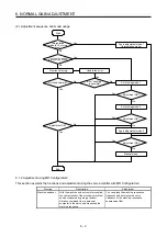
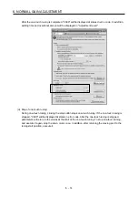
6.2 One-touch tuning
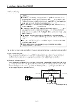
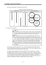
POINT
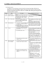
After the one-touch tuning is completed, "Gain adjustment mode selection" in
[Pr. PA08] will be set to "2 gain adjustment mode 2 (_ _ _ 4)". To estimate [Pr.
PB06 Load to motor inertia ratio/load to motor mass ratio], set "Gain adjustment
mode selection" in [Pr. PA08] to "Auto tuning mode 1 (_ _ _ 1)".
When executing the one-touch tuning, check the [Pr. PA21 One-touch tuning
function selection] is "_ _ _ 1" (initial value).
At start of the one-touch tuning, only when "Auto tuning mode 1 (_ _ _ 1)" or "2
gain adjustment mode 1 (interpolation mode) (_ _ _ 0)" of "Gain adjustment
mode selection" is selected in [Pr. PA08], [Pr. PB06 Load to motor inertia ratio]
will be estimated.
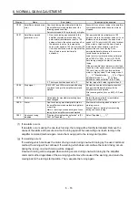
The amplifier command method can be used with the servo amplifier with
software version C1 or later and MR Configurator2 with software version 1.45X
or later.
When the one-touch tuning is executed in the amplifier command method, MR
Configurator2 is required.
For MR-J4-03A6(-RJ) servo amplifier, one-touch tuning by the amplifier
command method is not available.
The one-touch tuning includes two methods: the user command method and the amplifier command method.
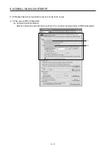
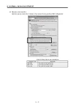
(1) User command method
You can execute the one-touch tuning with MR Configurator2 or push buttons. The user command
method performs one-touch tuning by inputting commands from outside the servo amplifier.
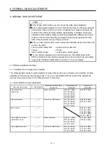
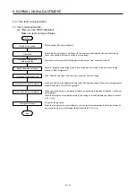
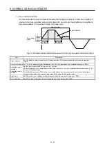
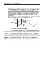
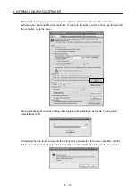
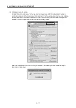
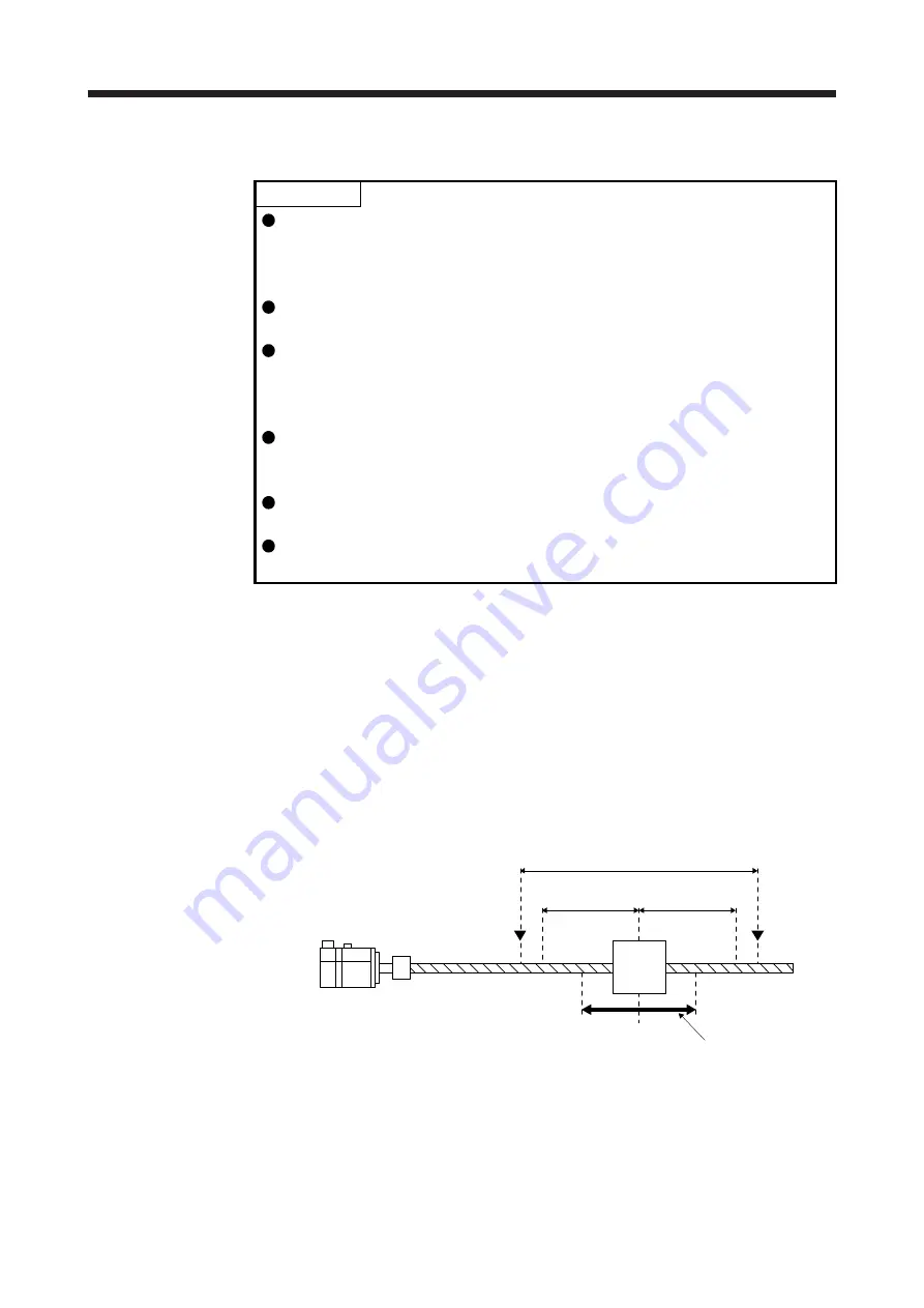
(2) Amplifier command method
You can execute the one-touch tuning with MR Configurator2. In the amplifier command method, when
you simply input a travel distance (permissible travel distance) that collision against the equipment does
not occur during servo motor driving, a command for the optimum tuning will be generated inside the
servo amplifier to perform one-touch tuning.
Servo motor
Moving
part
Movable range
Tuning start position
Movable range at tuning
Permissible
travel distance
Limit switch
Permissible
travel distance
Limit switch
Summary of Contents for MR-J4-100A(-RJ)
Page 19: ...10 MEMO ...
Page 75: ...1 FUNCTIONS AND CONFIGURATION 1 56 MEMO ...
Page 83: ...2 INSTALLATION 2 8 MEMO ...
Page 159: ...3 SIGNALS AND WIRING 3 76 MEMO ...
Page 203: ...4 STARTUP 4 44 MEMO ...
Page 351: ...7 SPECIAL ADJUSTMENT FUNCTIONS 7 40 MEMO ...
Page 365: ...8 TROUBLESHOOTING 8 14 MEMO ...
Page 387: ...9 DIMENSIONS 9 22 MEMO ...
Page 403: ...10 CHARACTERISTICS 10 16 MEMO ...
Page 553: ...12 ABSOLUTE POSITION DETECTION SYSTEM 12 30 MEMO ...
Page 567: ...13 USING STO FUNCTION 13 14 MEMO ...
Page 607: ...14 COMMUNICATION FUNCTION MITSUBISHI ELECTRIC GENERAL PURPOSE AC SERVO PROTOCOL 14 40 MEMO ...
Page 639: ...15 USING A LINEAR SERVO MOTOR 15 32 MEMO ...
Page 767: ...18 MR J4 03A6 RJ SERVO AMPLIFIER 18 84 MEMO ...
Page 856: ...APPENDIX App 41 ...
Page 905: ...MEMO ...


