

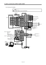
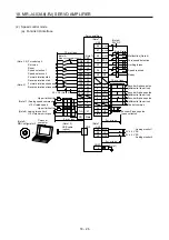
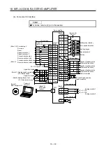

18. MR-J4-03A6(-RJ) SERVO AMPLIFIER
18 - 21
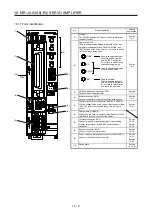
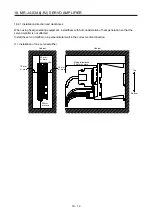
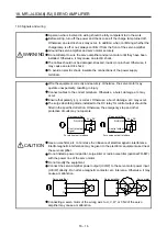
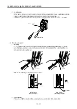
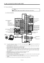
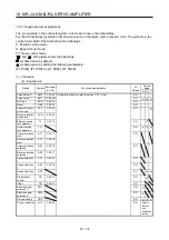
2) Inserting wire
When using solid wire, insert the wire to the end. When using stranded wire, insert the wire to the
end with pushing down the release button with a small flat head screwdriver, etc.
The following show a connection example when using stranded wire to the CNP 1 connector.
Release button
Stranded wire
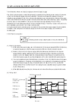
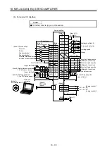
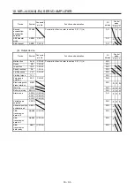
(c) Mounting connector
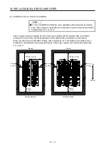
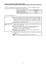
1) Mounting
Fit the CNP1 connector when the servo amplifier is fixed. While pushing the connector, make
sure that the connector is locked to the top and bottom of the socket. After that, check that the
connector cannot be pulled out.
Locked
Lock hook
Refer to the following example for a status of lock.
Unlocked
Locked
Good example
(Both are locked.)
Bad example
(Bottom is not locked.)
Locked
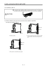
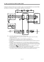
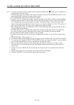
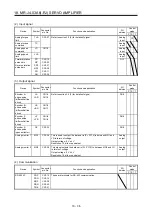
2) Disconnection
Pull out the CNP1 connector after unlocking the top and bottom of the connector.
Summary of Contents for MR-J4-100A(-RJ)
Page 19: ...10 MEMO ...
Page 75: ...1 FUNCTIONS AND CONFIGURATION 1 56 MEMO ...
Page 83: ...2 INSTALLATION 2 8 MEMO ...
Page 159: ...3 SIGNALS AND WIRING 3 76 MEMO ...
Page 203: ...4 STARTUP 4 44 MEMO ...
Page 351: ...7 SPECIAL ADJUSTMENT FUNCTIONS 7 40 MEMO ...
Page 365: ...8 TROUBLESHOOTING 8 14 MEMO ...
Page 387: ...9 DIMENSIONS 9 22 MEMO ...
Page 403: ...10 CHARACTERISTICS 10 16 MEMO ...
Page 553: ...12 ABSOLUTE POSITION DETECTION SYSTEM 12 30 MEMO ...
Page 567: ...13 USING STO FUNCTION 13 14 MEMO ...
Page 607: ...14 COMMUNICATION FUNCTION MITSUBISHI ELECTRIC GENERAL PURPOSE AC SERVO PROTOCOL 14 40 MEMO ...
Page 639: ...15 USING A LINEAR SERVO MOTOR 15 32 MEMO ...
Page 767: ...18 MR J4 03A6 RJ SERVO AMPLIFIER 18 84 MEMO ...
Page 856: ...APPENDIX App 41 ...
Page 905: ...MEMO ...


