

11. OPTIONS AND PERIPHERAL EQUIPMENT
11 - 26
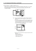
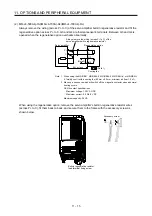
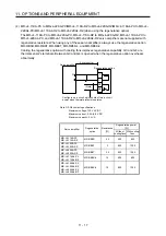
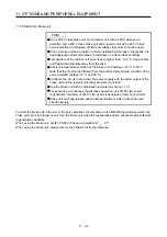
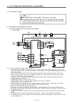
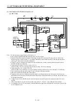
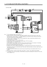
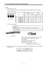
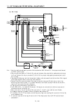
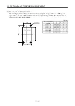
(b) When connecting two brake units to a servo amplifier
POINT
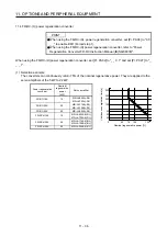
To use brake units with a parallel connection, use two sets of FR-BU2 brake
unit. Combination with other brake unit results in alarm occurrence or
malfunction.
Always connect the terminals for master/slave (MSG to MSG, SD to SD)
between the two brake units.
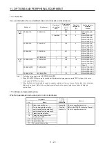
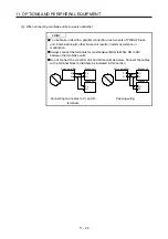
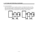
Do not connect the converter unit and brake units as below. Connect the cables
with a terminal block to distribute as indicated in this section.
N/-
P/+
Brake unit
Brake unit
Servo amplifier
P+
N-
N/-
P/+
Connecting two cables to P+ and N-
terminals
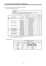
N/-
P/+
Brake unit
Brake unit
Servo amplifier
P+
N-
N/-
P/+
Passing wiring
Summary of Contents for MR-J4-100A(-RJ)
Page 19: ...10 MEMO ...
Page 75: ...1 FUNCTIONS AND CONFIGURATION 1 56 MEMO ...
Page 83: ...2 INSTALLATION 2 8 MEMO ...
Page 159: ...3 SIGNALS AND WIRING 3 76 MEMO ...
Page 203: ...4 STARTUP 4 44 MEMO ...
Page 351: ...7 SPECIAL ADJUSTMENT FUNCTIONS 7 40 MEMO ...
Page 365: ...8 TROUBLESHOOTING 8 14 MEMO ...
Page 387: ...9 DIMENSIONS 9 22 MEMO ...
Page 403: ...10 CHARACTERISTICS 10 16 MEMO ...
Page 553: ...12 ABSOLUTE POSITION DETECTION SYSTEM 12 30 MEMO ...
Page 567: ...13 USING STO FUNCTION 13 14 MEMO ...
Page 607: ...14 COMMUNICATION FUNCTION MITSUBISHI ELECTRIC GENERAL PURPOSE AC SERVO PROTOCOL 14 40 MEMO ...
Page 639: ...15 USING A LINEAR SERVO MOTOR 15 32 MEMO ...
Page 767: ...18 MR J4 03A6 RJ SERVO AMPLIFIER 18 84 MEMO ...
Page 856: ...APPENDIX App 41 ...
Page 905: ...MEMO ...


