


11. OPTIONS AND PERIPHERAL EQUIPMENT
11 - 49
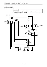
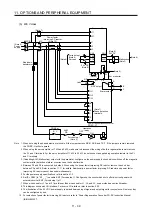
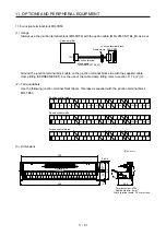
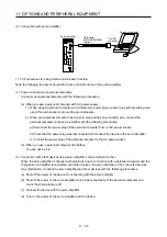
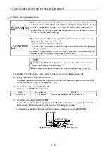
(5) Other precautions
(a) When using the FR-CV-(H), always install the dedicated stand-alone reactor (FR-CVL-(H)). Do not
use the power factor improving AC reactor (FR-HAL-(H)) or Power factor improving DC reactor (FR-
HEL-(H)).
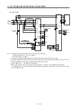
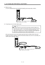
(b) The inputs/outputs (main circuits) of the FR-CV-(H) and servo amplifiers include high-frequency
components and may provide electromagnetic wave interference to communication equipment (such
as AM radios) used near them. In this case, interference can be reduced by installing the radio noise
filter (FR-BIF(-H)) or line noise filter (FR-BSF01, FR-BLF).
(c) The overall wiring length for connection of the DC power supply between the FR-CV-(H) and servo
amplifiers should be 5 m or less, and the wiring must be twisted.
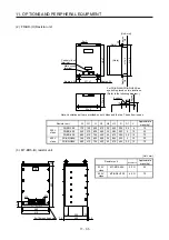
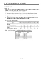
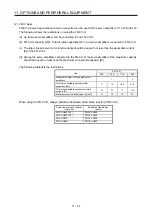
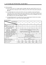
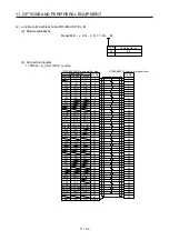
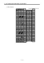
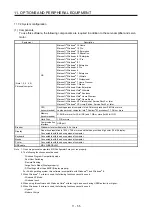
(6) Specifications
Power regeneration
common converter
FR-CV-_
Item
7.5K 11K 15K 22K 30K 37K 55K
Total of connectable servo amplifier
capacities
[kW] 3.75
5.5
7.5
11
15
18.5
27.5
Maximum servo amplifier capacity
[kW]
3.5
5
7
11
15
15
22
Output
Total of connectable servo
motor rated currents
[A]
33 46 61 90 115 145
215
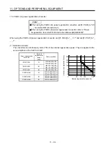
Regenerative
braking torque
Short-time rating
Total capacity of applicable servo motors, 300% torque, 60 s (Note 1)
Continuous rating
100% torque
Power
supply
Rated input AC voltage/frequency
3-phase 200 V AC to 220 V AC, 50 Hz, 200 V AC to 230 V AC, 60 Hz
Permissible AC voltage fluctuation
3-phase 170 V AC to 242 V AC, 50 Hz, 170 V AC to 253 V AC, 60 Hz
Permissible frequency fluctuation
±5%
Power supply capacity (Note 2) [kVA]
17
20
28
41
52
66
100
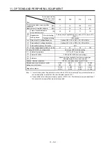
IP rating (JEM 1030), cooling method
Open type (IP00), forced cooling
Environment
Ambient temperature
-10 °C to 50 °C (non-freezing)
Ambient humidity
5 %RH to 90 %RH (non-condensing)
Ambience
Indoors (no direct sunlight), free from corrosive gas, flammable gas, oil mist, dust,
and dirt
Altitude, vibration resistance
1000 m or less above sea level, 5.9 m/s
2
Molded-case circuit breaker or earth-
leakage current breaker
30 AF
30 A
50 AF
50 A
100 AF
75 A
100 AF
100 A
125AF
125 A
125AF
125 A
225 AF
175 A
Magnetic contactor
S-N20
S-T21
S-N35
S-T35
S-N50
S-T50
S-N65
S-T65
S-N80
S-T80
S-N95
S-T100
S-N125
Summary of Contents for MR-J4-100A(-RJ)
Page 19: ...10 MEMO ...
Page 75: ...1 FUNCTIONS AND CONFIGURATION 1 56 MEMO ...
Page 83: ...2 INSTALLATION 2 8 MEMO ...
Page 159: ...3 SIGNALS AND WIRING 3 76 MEMO ...
Page 203: ...4 STARTUP 4 44 MEMO ...
Page 351: ...7 SPECIAL ADJUSTMENT FUNCTIONS 7 40 MEMO ...
Page 365: ...8 TROUBLESHOOTING 8 14 MEMO ...
Page 387: ...9 DIMENSIONS 9 22 MEMO ...
Page 403: ...10 CHARACTERISTICS 10 16 MEMO ...
Page 553: ...12 ABSOLUTE POSITION DETECTION SYSTEM 12 30 MEMO ...
Page 567: ...13 USING STO FUNCTION 13 14 MEMO ...
Page 607: ...14 COMMUNICATION FUNCTION MITSUBISHI ELECTRIC GENERAL PURPOSE AC SERVO PROTOCOL 14 40 MEMO ...
Page 639: ...15 USING A LINEAR SERVO MOTOR 15 32 MEMO ...
Page 767: ...18 MR J4 03A6 RJ SERVO AMPLIFIER 18 84 MEMO ...
Page 856: ...APPENDIX App 41 ...
Page 905: ...MEMO ...


