


19. MR-D01 EXTENSION I/O UNIT
19 - 13
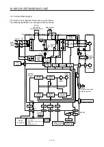
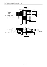
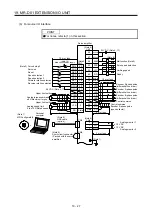
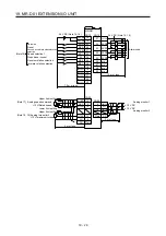
19.5 Signals and wiring
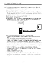
POINT
Input signals of the servo amplifier are valid even when the MR-D01 has been
connected. When the same input devices have been assigned to the servo
amplifier and MR-D01 and both input signals are turned on, the input signal that
has turned on first is enabled. Even though turning off one of the input signals
that have been turned on is attempted, the input signal cannot be turned off.
Refer to the following table for details. The following table shows ST1 (Forward
rotation start) as an example.
Device
(Note)
Servo amplifier
(Note)
MR-D01
Servo motor
ST1
0 0
Stop
0 1
Forward
rotation
1 0
Forward
rotation
1 1
Forward
rotation
Note.
0: Off
1: On
Summary of Contents for MR-J4-100A(-RJ)
Page 19: ...10 MEMO ...
Page 75: ...1 FUNCTIONS AND CONFIGURATION 1 56 MEMO ...
Page 83: ...2 INSTALLATION 2 8 MEMO ...
Page 159: ...3 SIGNALS AND WIRING 3 76 MEMO ...
Page 203: ...4 STARTUP 4 44 MEMO ...
Page 351: ...7 SPECIAL ADJUSTMENT FUNCTIONS 7 40 MEMO ...
Page 365: ...8 TROUBLESHOOTING 8 14 MEMO ...
Page 387: ...9 DIMENSIONS 9 22 MEMO ...
Page 403: ...10 CHARACTERISTICS 10 16 MEMO ...
Page 553: ...12 ABSOLUTE POSITION DETECTION SYSTEM 12 30 MEMO ...
Page 567: ...13 USING STO FUNCTION 13 14 MEMO ...
Page 607: ...14 COMMUNICATION FUNCTION MITSUBISHI ELECTRIC GENERAL PURPOSE AC SERVO PROTOCOL 14 40 MEMO ...
Page 639: ...15 USING A LINEAR SERVO MOTOR 15 32 MEMO ...
Page 767: ...18 MR J4 03A6 RJ SERVO AMPLIFIER 18 84 MEMO ...
Page 856: ...APPENDIX App 41 ...
Page 905: ...MEMO ...


