
16. USING A DIRECT DRIVE MOTOR
16 - 4
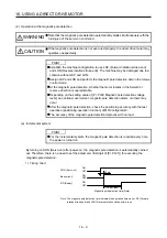
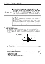
CAUTION
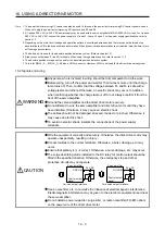
When using the regenerative resistor, switch power off with the alarm signal.
Otherwise, a transistor fault or the like may overheat the regenerative resistor,
causing a fire.
Do not modify the equipment.
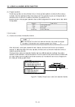
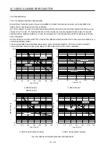
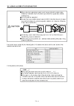
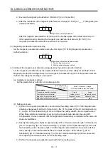
Connect the servo amplifier power output (U/V/W) to the direct drive motor power
input (U/V/W) directly. Do not let a magnetic contactor, etc. intervene. Otherwise,
it may cause a malfunction.
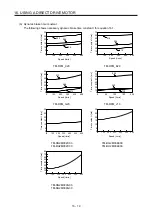
Servo amplifier
Servo amplifier
Direct drive motor
Direct drive motor
U
M
V
W
U
V
W
U
M
V
W
U
V
W
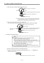
Connecting a servo motor of the wrong axis to U, V, W, or CN2 of the servo
amplifier may cause a malfunction.
Before wiring, switch operation, etc., eliminate static electricity. Otherwise, it may
cause a malfunction.
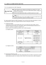
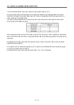
This section does not describe the following items. For details of the items, refer to each section of the
detailed description field.
Item Detailed
explanation
Input power supply circuit
Section 3.1
Explanation of power supply system
Section 3.3
Signal (device) explanations Section
3.5
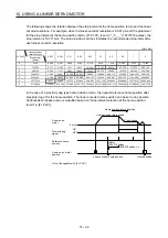
Alarm occurrence timing chart
Section 3.8
Interface Section
3.9
Grounding Section
3.11
Display and operation sections
Section 4.5
Parameter Chapter
5
Troubleshooting Chapter
8
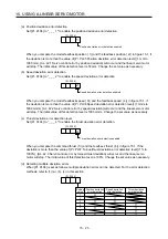
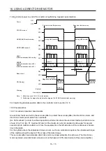
16.3 Operation and functions
POINT
When using the direct drive motor, set [Pr. PA01] to "_ _ 6 _".
For the test operation, refer to section 4.2.3, 4.3.3, 4.4.3, and 4.5.9.
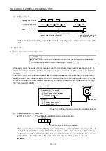
After power on, the Z-phase mark of the direct drive motor must pass the
connector area once. In a system which prevents the direct drive motor from
making a full rotation, install the direct drive motor in a position where the Z-
phase mark can pass over the connector area.
Summary of Contents for MR-J4-100A(-RJ)
Page 19: ...10 MEMO ...
Page 75: ...1 FUNCTIONS AND CONFIGURATION 1 56 MEMO ...
Page 83: ...2 INSTALLATION 2 8 MEMO ...
Page 159: ...3 SIGNALS AND WIRING 3 76 MEMO ...
Page 203: ...4 STARTUP 4 44 MEMO ...
Page 351: ...7 SPECIAL ADJUSTMENT FUNCTIONS 7 40 MEMO ...
Page 365: ...8 TROUBLESHOOTING 8 14 MEMO ...
Page 387: ...9 DIMENSIONS 9 22 MEMO ...
Page 403: ...10 CHARACTERISTICS 10 16 MEMO ...
Page 553: ...12 ABSOLUTE POSITION DETECTION SYSTEM 12 30 MEMO ...
Page 567: ...13 USING STO FUNCTION 13 14 MEMO ...
Page 607: ...14 COMMUNICATION FUNCTION MITSUBISHI ELECTRIC GENERAL PURPOSE AC SERVO PROTOCOL 14 40 MEMO ...
Page 639: ...15 USING A LINEAR SERVO MOTOR 15 32 MEMO ...
Page 767: ...18 MR J4 03A6 RJ SERVO AMPLIFIER 18 84 MEMO ...
Page 856: ...APPENDIX App 41 ...
Page 905: ...MEMO ...


