

6. NORMAL GAIN ADJUSTMENT
6 - 23
6.3 Auto tuning
6.3.1 Auto tuning mode
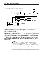
The servo amplifier has a real-time auto tuning function which estimates the machine characteristic (load to
motor inertia ratio) in real time and automatically sets the optimum gains according to that value. This
function permits ease of gain adjustment of the servo amplifier.
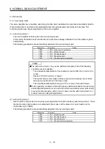
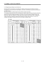
(1) Auto tuning mode 1
The servo amplifier is factory-set to the auto tuning mode 1.
In this mode, the load to motor inertia ratio of a machine is always estimated to set the optimum gains
automatically.
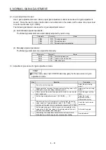
The following parameters are automatically adjusted in the auto tuning mode 1.
Parameter Symbol
Name
PB06
GD2
Load to motor inertia ratio
PB07
PG1
Model loop gain
PB08
PG2
Position loop gain
PB09
VG2
Speed loop gain
PB10
VIC
Speed integral compensation
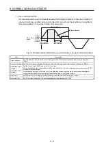
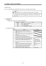
POINT
The auto tuning mode 1 may not be performed properly if all of the following
conditions are not satisfied.
The acceleration/deceleration time constant to reach 2000 r/min (mm/s) is 5 s
or less.
Speed is 150 r/min (mm/s) or higher.
The load to servo motor (mass of linear servo motor's primary side or direct
drive motor) inertia ratio is 100 times or less.
The acceleration/deceleration torque is 10% or more of the rated torque.
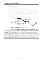
Under operating conditions which will impose sudden disturbance torque during
acceleration/deceleration or on a machine which is extremely loose, auto tuning
may not function properly, either. In such cases, use the auto tuning mode 2 or
manual mode to make gain adjustment.
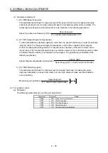
(2) Auto tuning mode 2
Use the auto tuning mode 2 when proper gain adjustment cannot be made by auto tuning mode 1. Since
the load to motor inertia ratio is not estimated in this mode, set the value of a correct load to motor
inertia ratio in [Pr. PB06].
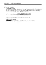
The following parameters are automatically adjusted in the auto tuning mode 2.
Parameter Symbol
Name
PB07
PG1
Model loop gain
PB08
PG2
Position loop gain
PB09
VG2
Speed loop gain
PB10
VIC
Speed integral compensation
Summary of Contents for MR-J4-100A(-RJ)
Page 19: ...10 MEMO ...
Page 75: ...1 FUNCTIONS AND CONFIGURATION 1 56 MEMO ...
Page 83: ...2 INSTALLATION 2 8 MEMO ...
Page 159: ...3 SIGNALS AND WIRING 3 76 MEMO ...
Page 203: ...4 STARTUP 4 44 MEMO ...
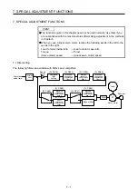
Page 351: ...7 SPECIAL ADJUSTMENT FUNCTIONS 7 40 MEMO ...
Page 365: ...8 TROUBLESHOOTING 8 14 MEMO ...
Page 387: ...9 DIMENSIONS 9 22 MEMO ...
Page 403: ...10 CHARACTERISTICS 10 16 MEMO ...
Page 553: ...12 ABSOLUTE POSITION DETECTION SYSTEM 12 30 MEMO ...
Page 567: ...13 USING STO FUNCTION 13 14 MEMO ...
Page 607: ...14 COMMUNICATION FUNCTION MITSUBISHI ELECTRIC GENERAL PURPOSE AC SERVO PROTOCOL 14 40 MEMO ...
Page 639: ...15 USING A LINEAR SERVO MOTOR 15 32 MEMO ...
Page 767: ...18 MR J4 03A6 RJ SERVO AMPLIFIER 18 84 MEMO ...
Page 856: ...APPENDIX App 41 ...
Page 905: ...MEMO ...


