

APPENDIX
App. - 45
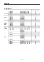
Setting
value
Output item
Description
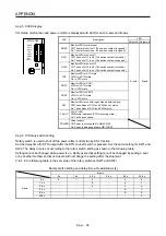
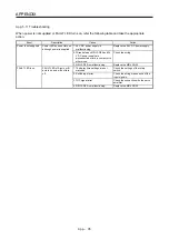
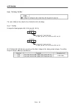
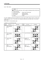
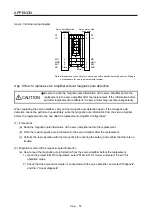
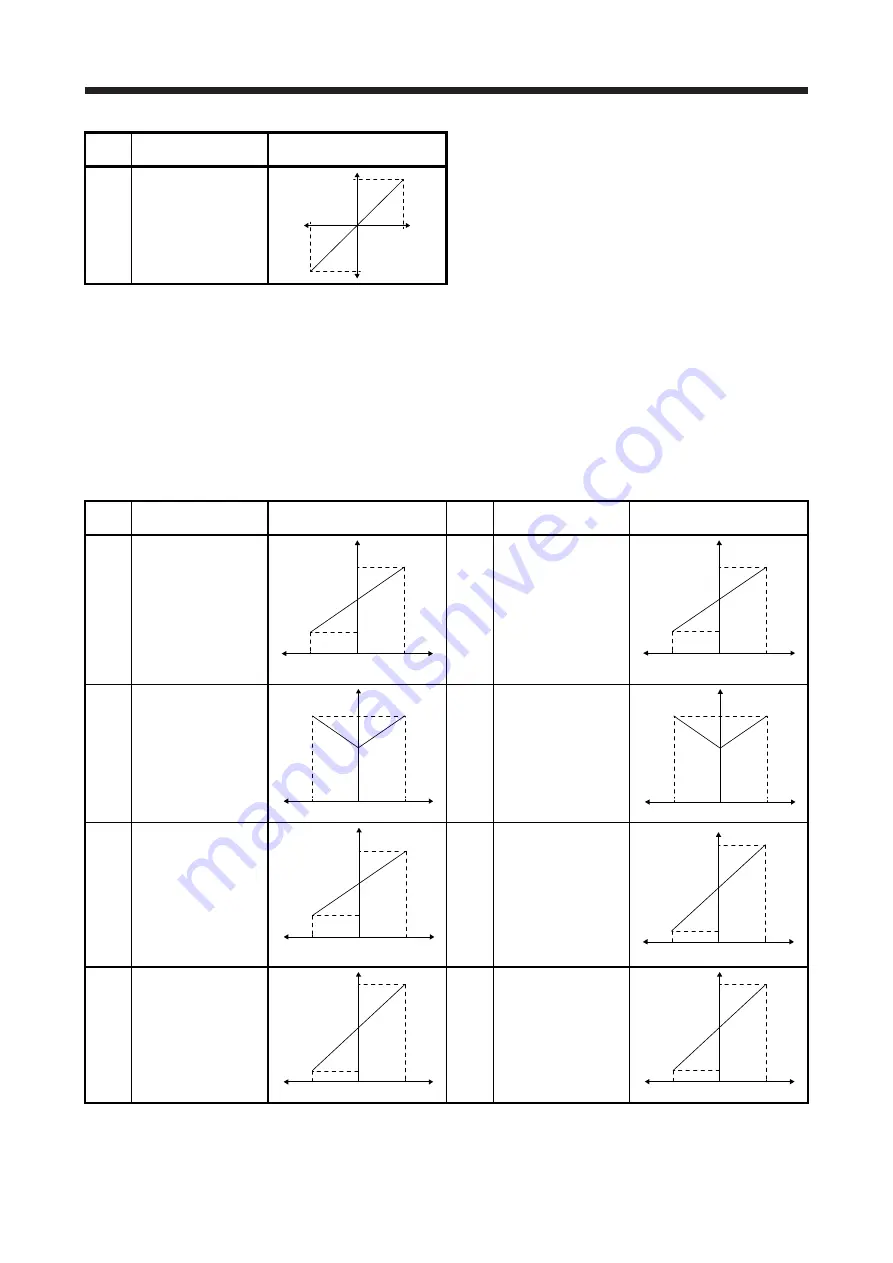
17
Internal temperature of
encoder
(±10 V/±128
˚
C)
128 [°C]
-128 [°C]
0
10 [V]
-10 [V]
Note 1. Encoder pulse unit.
2.
Available in position control mode
3. This cannot be used in the torque control mode.
4. This can be used with MR Configurator2 with software version 1.19V or later.
5. This cannot be used in the speed control mode.
6. Output in the load-side encoder unit for the fully closed loop control. Output in the servo motor encoder unit for the semi closed
loop control.
7. For 400 V class servo amplifier, the bus voltage b8 V/800 V.
8. For details on the maximum current command (maximum torque) for ±8 V, refer to app. 7.4 for details.
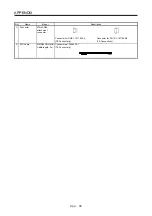
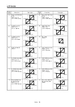
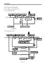
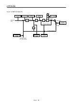
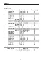
(2) MR-J4-03A6(-RJ)
Setting
value
Output item
Description
Setting
value
Output item
Description
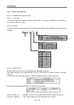
00
Servo motor speed
(5 V ± 3 V/max. speed)
CW
direction
CCW direction
5 [V]
8 [V]
2 [V]
0
Maximum speed
Maximum speed
01
Torque (Note 5)
(5 V ± 3 V/max. torque)
Maximum torque
Maximum torque
5 [V]
8 [V]
2 [V]
0
Power running
in CW
direction
Power running in
CCW direction
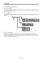
02
Servo motor speed
(5 V + 3 V/max. speed)
5 [V]
8 [V]
0
Maximum speed
CW direction
CCW direction
Maximum speed
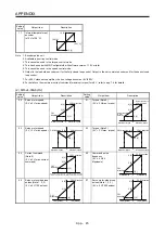
03
Torque (Note 5)
(5 V + 3 V/max. torque)
5 [V]
8 [V]
0
Maximum torque
CW direction
CCW direction
Maximum torque
04 Current
command
(Note 5)
(5 V ± 3 V/max. current
command)
5 [V]
8 [V]
2 [V]
0
Maximum current command
(Maximum torque command)
CW
direction
CCW direction
Maximum current command
(Maximum torque command)
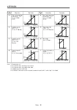
05 Command
pulse
frequency
(5 V ± 4 V/±4
Mpulses/s)
4 [Mpulse/s]
4 [Mpulse/s]
5 [V]
9 [V]
1 [V]
0
CW
direction
CCW direction
06
Servo motor-side droop
pulses (Note 1, 2, 3)
(5 V ± 4 V/100 pulses)
100 [pulse]
100 [pulse]
5 [V]
9 [V]
1 [V]
0
CW
direction
CCW direction
07
Servo motor-side droop
pulses (Note 1, 2, 3)
(5 V ± 4 V/1000 pulses)
1000 [pulse]
1000 [pulse]
5 [V]
9 [V]
1 [V]
0
CW
direction
CCW direction
Summary of Contents for MR-J4-100A(-RJ)
Page 19: ...10 MEMO ...
Page 75: ...1 FUNCTIONS AND CONFIGURATION 1 56 MEMO ...
Page 83: ...2 INSTALLATION 2 8 MEMO ...
Page 159: ...3 SIGNALS AND WIRING 3 76 MEMO ...
Page 203: ...4 STARTUP 4 44 MEMO ...
Page 351: ...7 SPECIAL ADJUSTMENT FUNCTIONS 7 40 MEMO ...
Page 365: ...8 TROUBLESHOOTING 8 14 MEMO ...
Page 387: ...9 DIMENSIONS 9 22 MEMO ...
Page 403: ...10 CHARACTERISTICS 10 16 MEMO ...
Page 553: ...12 ABSOLUTE POSITION DETECTION SYSTEM 12 30 MEMO ...
Page 567: ...13 USING STO FUNCTION 13 14 MEMO ...
Page 607: ...14 COMMUNICATION FUNCTION MITSUBISHI ELECTRIC GENERAL PURPOSE AC SERVO PROTOCOL 14 40 MEMO ...
Page 639: ...15 USING A LINEAR SERVO MOTOR 15 32 MEMO ...
Page 767: ...18 MR J4 03A6 RJ SERVO AMPLIFIER 18 84 MEMO ...
Page 856: ...APPENDIX App 41 ...
Page 905: ...MEMO ...


