
3. SIGNALS AND WIRING
3 - 27
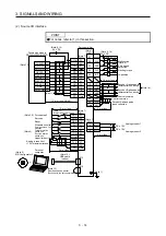
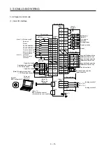
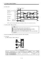
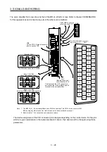
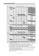
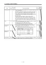
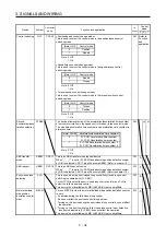
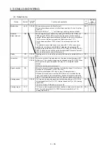
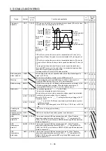
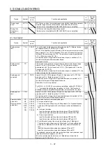
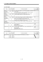
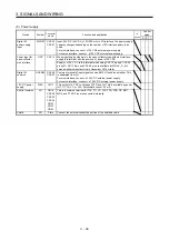
3.4 Connectors and pin assignment
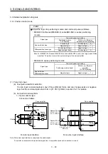
POINT
The pin assignment of the connectors is as viewed from the cable connector
wiring section.
For the STO I/O signal connector (CN8), refer to chapter 13.
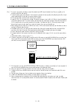
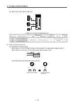
For the CN1 connector, securely connect the external conductive portion of the
shielded cable to the ground plate and fix it to the connector shell.
Screw
Screw
Ground plate
Cable
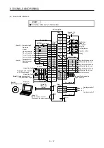
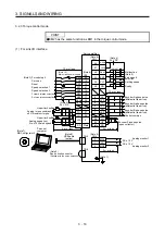
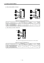
PP (CN1-10 pin)/NP (CN1-35 pin) and PP2 (CN1-37 pin)/NP2 (CN1-38 pin) are
exclusive. They cannot be used together.
Summary of Contents for MR-J4-100A(-RJ)
Page 19: ...10 MEMO ...
Page 75: ...1 FUNCTIONS AND CONFIGURATION 1 56 MEMO ...
Page 83: ...2 INSTALLATION 2 8 MEMO ...
Page 159: ...3 SIGNALS AND WIRING 3 76 MEMO ...
Page 203: ...4 STARTUP 4 44 MEMO ...
Page 351: ...7 SPECIAL ADJUSTMENT FUNCTIONS 7 40 MEMO ...
Page 365: ...8 TROUBLESHOOTING 8 14 MEMO ...
Page 387: ...9 DIMENSIONS 9 22 MEMO ...
Page 403: ...10 CHARACTERISTICS 10 16 MEMO ...
Page 553: ...12 ABSOLUTE POSITION DETECTION SYSTEM 12 30 MEMO ...
Page 567: ...13 USING STO FUNCTION 13 14 MEMO ...
Page 607: ...14 COMMUNICATION FUNCTION MITSUBISHI ELECTRIC GENERAL PURPOSE AC SERVO PROTOCOL 14 40 MEMO ...
Page 639: ...15 USING A LINEAR SERVO MOTOR 15 32 MEMO ...
Page 767: ...18 MR J4 03A6 RJ SERVO AMPLIFIER 18 84 MEMO ...
Page 856: ...APPENDIX App 41 ...
Page 905: ...MEMO ...


