

18. MR-J4-03A6(-RJ) SERVO AMPLIFIER
18 - 22
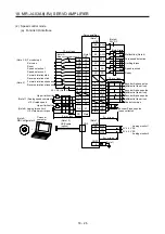
18.3.3 Selection of main circuit power supply/control circuit power supply
The inrush current at power on will be large because a resistance for protecting inrush current is not built-in
in the main circuit power supply of the servo amplifier. The main circuit capacitor capacity of the servo
amplifier is approximately 270
μ
F. When the load characteristic (overcurrent protection criteria) of the power
unit is current fold back method, the power cannot be started. Be careful when selecting a power. Especially
when the power is turned ON/OFF on the power unit output side, approximately 100
μ
s to 300
μ
s
instantaneous current will flowed at power on due to capacitor charge. Therefore, a power unit such as one
which operates overcurrent at 1 ms or less cannot be used.
A circuit to protect inrush current at power on is built-in in the control circuit power supply of servo amplifier.
In addition, when using main circuit power supply and control circuit power supply, use a reinforced
insulating type.
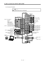
18.3.4 Power-on sequence
POINT
The voltage of analog monitor output, output signal, etc. may be unstable at
power-on.
(1) Power-on procedure
1) When wiring the power supply, use a circuit protector for the power supply (24/PM). Configure up
an external sequence so that the relay connected to PM turns off when an alarm occurs.
2) Switch on the control circuit power supply (24/0) simultaneously with the main circuit power
supply (PM/0) or before switching on the main circuit power supply. If the main circuit power
supply is not on, the display shows the corresponding warning. However, by switching on the
main circuit power supply, the warning disappears and the servo amplifier will operate properly.
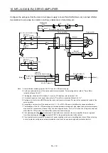
3) The servo amplifier receives the SON (Servo-on) within 2.5 s to 3.5 s after the main circuit power
supply is switched on. Therefore, when SON (Servo-on) is switched on simultaneously with the
main circuit power supply, the base circuit will switch on in about 2.5 s to 3.5 s, and the RD
(Ready) will switch on in further about 5 ms, making the servo amplifier ready to operate. (Refer
to (2) in this section.)
4) When RES (Reset) is switched on, the base circuit is shut off and the servo motor shaft coasts.
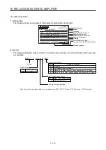
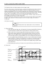
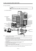
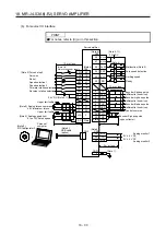
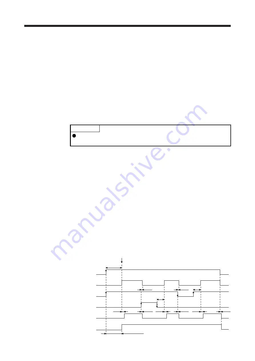
(2) Timing chart
95 ms
95 ms
RD (Ready)
RES (Reset)
SON (Servo-on)
OFF
ON
OFF
ON
ON
OFF
Base circuit
OFF
ON
power supply
OFF
ON
10 ms
5 ms
10 ms
10 ms
5 ms
10 ms
5 ms
10 ms
(2.5 s to 3.5 s)
SON (Servo-on) accepted
Main circuit
Control circuit
Alarm (OFF)
No alarm (ON)
ALM
(Malfunction)
2.5 s to 3.5 s
Summary of Contents for MR-J4-100A(-RJ)
Page 19: ...10 MEMO ...
Page 75: ...1 FUNCTIONS AND CONFIGURATION 1 56 MEMO ...
Page 83: ...2 INSTALLATION 2 8 MEMO ...
Page 159: ...3 SIGNALS AND WIRING 3 76 MEMO ...
Page 203: ...4 STARTUP 4 44 MEMO ...
Page 351: ...7 SPECIAL ADJUSTMENT FUNCTIONS 7 40 MEMO ...
Page 365: ...8 TROUBLESHOOTING 8 14 MEMO ...
Page 387: ...9 DIMENSIONS 9 22 MEMO ...
Page 403: ...10 CHARACTERISTICS 10 16 MEMO ...
Page 553: ...12 ABSOLUTE POSITION DETECTION SYSTEM 12 30 MEMO ...
Page 567: ...13 USING STO FUNCTION 13 14 MEMO ...
Page 607: ...14 COMMUNICATION FUNCTION MITSUBISHI ELECTRIC GENERAL PURPOSE AC SERVO PROTOCOL 14 40 MEMO ...
Page 639: ...15 USING A LINEAR SERVO MOTOR 15 32 MEMO ...
Page 767: ...18 MR J4 03A6 RJ SERVO AMPLIFIER 18 84 MEMO ...
Page 856: ...APPENDIX App 41 ...
Page 905: ...MEMO ...


