

4. STARTUP
4 - 9
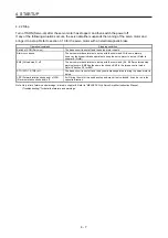
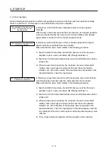
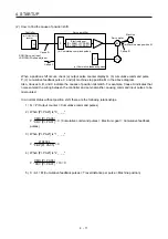
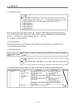
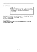
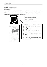
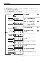
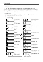
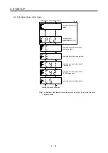
4.2.4 Parameter setting
POINT
The following encoder cables are of four-wire type. When using any of these
encoder cables, set [Pr. PC22] to "1 _ _ _" to select the four-wire type. Incorrect
setting will result in [AL. 16 Encoder initial communication error 1].
MR-EKCBL30M-L
MR-EKCBL30M-H
MR-EKCBL40M-H
MR-EKCBL50M-H
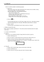
In the position control mode, the servo amplifier can be used by merely changing the basic setting
parameters ([Pr. PA _ _ ]) mainly.
As necessary, set other parameters.
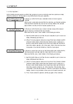
4.2.5 Actual operation
Start actual operation after confirmation of normal operation by test operation and completion of the
corresponding parameter settings. Perform a home position return as necessary.
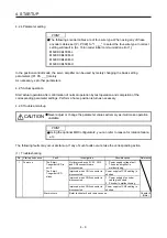
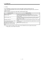
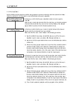
4.2.6 Trouble at start-up
CAUTION
Never adjust or change the parameter values extremely as it will make operation
unstable.
POINT
Using the optional MR Configurator2, you can refer to reason for rotation failure,
etc.
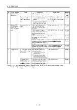
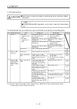
The following faults may occur at start-up. If any of such faults occurs, take the corresponding action.
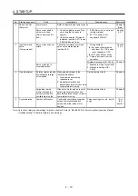
(1) Troubleshooting
No. Start-up
sequence
Fault
Investigation Possible
cause
Reference
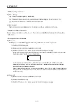
1 Power
on
The 5-digit,
7-segment LED is
not lit.
The 5-digit,
7-segment LED
blinks.
Not improved even if CN1, CN2
and CN3 connectors are
disconnected.
1. Power supply voltage fault
2. The servo amplifier is
malfunctioning.
Improved when CN1 connector is
disconnected.
Power supply of CN1 cabling is
shorted.
Improved when CN2 connector is
disconnected.
1. Power supply of encoder
cabling is shorted.
2. Encoder is malfunctioning.
Improved when CN3 connector is
disconnected.
Power supply of CN3 cabling is
shorted.
Alarm occurs.
Refer to chapter 8 and remove cause.
Chapter 8
(Note)
Summary of Contents for MR-J4-100A(-RJ)
Page 19: ...10 MEMO ...
Page 75: ...1 FUNCTIONS AND CONFIGURATION 1 56 MEMO ...
Page 83: ...2 INSTALLATION 2 8 MEMO ...
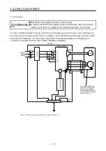
Page 159: ...3 SIGNALS AND WIRING 3 76 MEMO ...
Page 203: ...4 STARTUP 4 44 MEMO ...
Page 351: ...7 SPECIAL ADJUSTMENT FUNCTIONS 7 40 MEMO ...
Page 365: ...8 TROUBLESHOOTING 8 14 MEMO ...
Page 387: ...9 DIMENSIONS 9 22 MEMO ...
Page 403: ...10 CHARACTERISTICS 10 16 MEMO ...
Page 553: ...12 ABSOLUTE POSITION DETECTION SYSTEM 12 30 MEMO ...
Page 567: ...13 USING STO FUNCTION 13 14 MEMO ...
Page 607: ...14 COMMUNICATION FUNCTION MITSUBISHI ELECTRIC GENERAL PURPOSE AC SERVO PROTOCOL 14 40 MEMO ...
Page 639: ...15 USING A LINEAR SERVO MOTOR 15 32 MEMO ...
Page 767: ...18 MR J4 03A6 RJ SERVO AMPLIFIER 18 84 MEMO ...
Page 856: ...APPENDIX App 41 ...
Page 905: ...MEMO ...


