


5. PARAMETERS
5 - 29
No./symbol/
name
Setting
digit
Function
Initial
value
[unit]
Control
mode
P S T
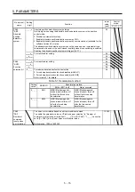
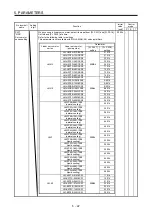
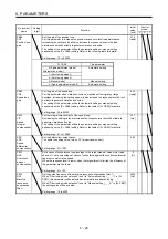
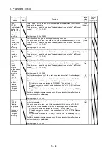
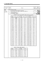
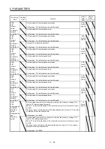
PB08
PG2
Position loop
gain
Set the gain of the position loop.
Set this parameter to increase the position response to level load disturbance.
Increasing the setting value will also increase the response level to the load
disturbance but will be liable to generate vibration and noise.
The setting of the parameter will be the automatic setting or manual setting
depending on the [Pr. PA08] setting. Refer to the following table for details.
Setting range: 1.0 to 2000.0
37.0
[rad/s]
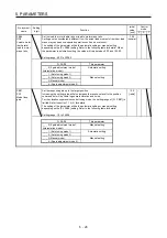
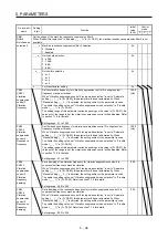
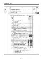
Pr. PA08
This parameter
_ _ _ 0 (2 gain adjustment mode 1
(interpolation mode))
Automatic setting
_ _ _ 1: (Auto tuning mode 1)
_ _ _ 2: (Auto tuning mode 2)
_ _ _ 3 (Manual mode)
Manual setting
_ _ _ 4: (2 gain adjustment mode 2)
Automatic setting
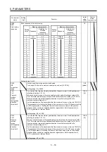
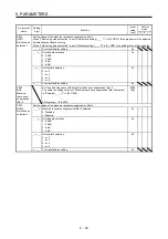
PB09
VG2
Speed loop
gain
Set the gain of the speed loop.
Set this parameter when vibration occurs on machines of low rigidity or large
backlash. Increasing the setting value will also increase the response level but will
be liable to generate vibration and noise.
The setting of the parameter will be the automatic setting or manual setting
depending on the [Pr. PA08] setting. Refer to the table of [Pr. PB08] for details.
Setting range: 20 to 65535
823
[rad/s]
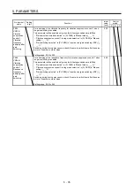
PB10
VIC
Speed
integral
compensation
Set the integral time constant of the speed loop.
Decreasing the setting value will increase the response level but will be liable to
generate vibration and noise.
The setting of the parameter will be the automatic setting or manual setting
depending on the [Pr. PA08] setting. Refer to the table of [Pr. PB08] for details.
Setting range: 0.1 to 1000.0
33.7
[ms]
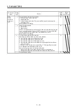
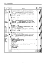
PB11
VDC
Speed
differential
compensation
Set the differential compensation.
To enable the setting value, turn on PC (proportional control).
Setting range: 0 to 1000
980
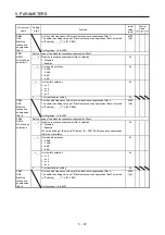
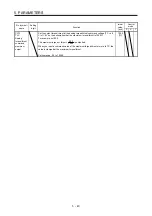
PB12
OVA
Overshoot
amount
compensation
Set a viscous friction torque in percentage to the rated torque at servo motor rated
speed. Or, set a percentage of viscous friction force against the continuous thrust at
linear servo motor rated speed.
When the response level is low or when the torque/thrust is limited, the efficiency of
the parameter may be lower.
Setting range: 0 to 100
0
[%]
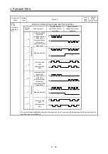
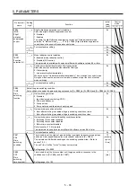
PB13
NH1
Machine
resonance
suppression
filter 1
Set the notch frequency of the machine resonance suppression filter 1.
When "Filter tuning mode selection" is set to "Automatic setting (_ _ _ 1)" in [Pr.
PB01], this parameter will be adjusted automatically by adaptive tuning.
When "Filter tuning mode selection" is set to "Manual setting (_ _ _ 2)" in [Pr. PB01],
the setting value will be enabled.
Setting range: 10 to 4500
4500
[Hz]
Summary of Contents for MR-J4-100A(-RJ)
Page 19: ...10 MEMO ...
Page 75: ...1 FUNCTIONS AND CONFIGURATION 1 56 MEMO ...
Page 83: ...2 INSTALLATION 2 8 MEMO ...
Page 159: ...3 SIGNALS AND WIRING 3 76 MEMO ...
Page 203: ...4 STARTUP 4 44 MEMO ...
Page 351: ...7 SPECIAL ADJUSTMENT FUNCTIONS 7 40 MEMO ...
Page 365: ...8 TROUBLESHOOTING 8 14 MEMO ...
Page 387: ...9 DIMENSIONS 9 22 MEMO ...
Page 403: ...10 CHARACTERISTICS 10 16 MEMO ...
Page 553: ...12 ABSOLUTE POSITION DETECTION SYSTEM 12 30 MEMO ...
Page 567: ...13 USING STO FUNCTION 13 14 MEMO ...
Page 607: ...14 COMMUNICATION FUNCTION MITSUBISHI ELECTRIC GENERAL PURPOSE AC SERVO PROTOCOL 14 40 MEMO ...
Page 639: ...15 USING A LINEAR SERVO MOTOR 15 32 MEMO ...
Page 767: ...18 MR J4 03A6 RJ SERVO AMPLIFIER 18 84 MEMO ...
Page 856: ...APPENDIX App 41 ...
Page 905: ...MEMO ...


