
4. STARTUP
4 - 10
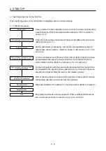
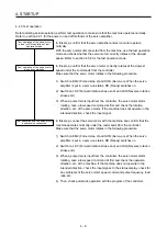
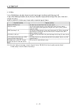
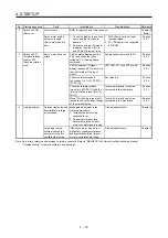
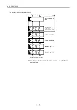
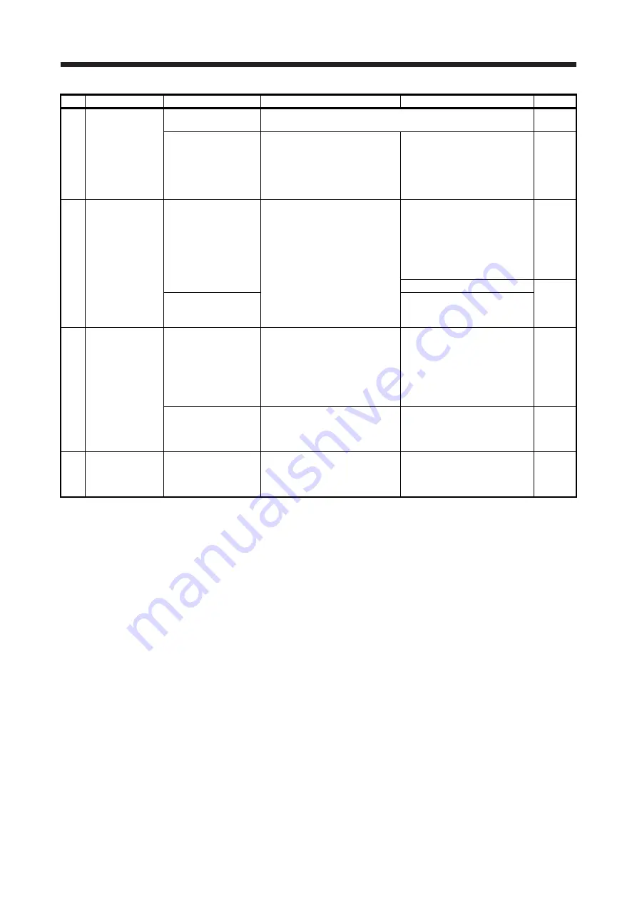
No. Start-up
sequence
Fault
Investigation Possible
cause
Reference
2
Switch on SON
(Servo-on).
Alarm occurs.
Refer to chapter 8 and remove cause.
Chapter 8
(Note)
Servo motor shaft is
not servo-locked.
(Servo motor shaft is
free.)
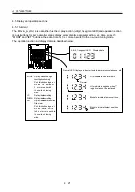
1. Check the display to see if the
servo amplifier is ready to
operate.
2. Check the external I/O signal
indication (section 4.5.7) to see
if SON (Servo-on) is on.
1. SON (Servo-on) is not input.
(wiring mistake)
2. 24 V DC power is not
supplied to DICOM.
Section
4.5.7
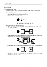
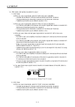
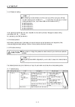
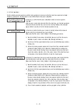
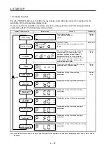
3 Input
command
pulse.
(Test operation)
Servo motor does not
rotate.
Check the cumulative command
pulse on the status display
(section 4.5.3).
1. Wiring mistake
(a) For open collector pulse
train input, 24 V DC power
is not supplied to OPC.
(b) LSP and LSN are not on.
2. Pulse is not input from the
controller.
Section
4.5.3
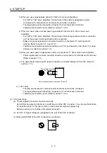
Mistake in setting of [Pr. PA13].
Chapter 5
Servo motor run in
reverse direction.
1. Mistake in wiring to controller.
2. Mistake in setting of [Pr.
PA14].
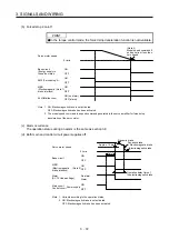
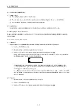
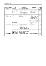
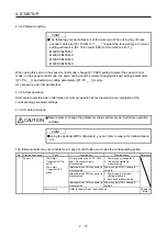
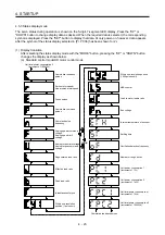
4 Gain
adjustment Rotation ripples (speed
fluctuations) are large
at low speed.
Make gain adjustment in the
following procedure.
1. Increase the auto tuning
response level.
2. Repeat acceleration and
deceleration three times or more
to complete auto tuning.
Gain adjustment fault
Chapter 6
Large load inertia
moment causes the
servo motor shaft to
oscillate side to side.
If the servo motor may be run with
safety, repeat acceleration and
deceleration three times or more to
complete auto tuning.
Gain adjustment fault
Chapter 6
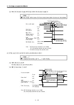
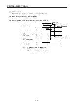
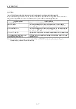
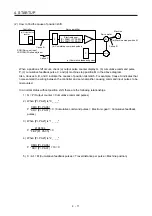
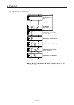
5
Cyclic operation
Position shift occurs
Confirm the cumulative command
pulses, cumulative feedback
pulses and actual servo motor
position.
Pulse counting error, etc. due to
noise.
(2) in
this
section
Note. Only a list of alarms and warnings is listed in chapter 8. Refer to "MELSERVO-J4 Servo Amplifier Instruction Manual
(Troubleshooting)" for details of alarms and warnings.
Summary of Contents for MR-J4-100A(-RJ)
Page 19: ...10 MEMO ...
Page 75: ...1 FUNCTIONS AND CONFIGURATION 1 56 MEMO ...
Page 83: ...2 INSTALLATION 2 8 MEMO ...
Page 159: ...3 SIGNALS AND WIRING 3 76 MEMO ...
Page 203: ...4 STARTUP 4 44 MEMO ...
Page 351: ...7 SPECIAL ADJUSTMENT FUNCTIONS 7 40 MEMO ...
Page 365: ...8 TROUBLESHOOTING 8 14 MEMO ...
Page 387: ...9 DIMENSIONS 9 22 MEMO ...
Page 403: ...10 CHARACTERISTICS 10 16 MEMO ...
Page 553: ...12 ABSOLUTE POSITION DETECTION SYSTEM 12 30 MEMO ...
Page 567: ...13 USING STO FUNCTION 13 14 MEMO ...
Page 607: ...14 COMMUNICATION FUNCTION MITSUBISHI ELECTRIC GENERAL PURPOSE AC SERVO PROTOCOL 14 40 MEMO ...
Page 639: ...15 USING A LINEAR SERVO MOTOR 15 32 MEMO ...
Page 767: ...18 MR J4 03A6 RJ SERVO AMPLIFIER 18 84 MEMO ...
Page 856: ...APPENDIX App 41 ...
Page 905: ...MEMO ...


