
14. COMMUNICATION FUNCTION (MITSUBISHI ELECTRIC GENERAL-PURPOSE AC SERVO PROTOCOL)
14 - 2
14.1 Structure
14.1.1 Configuration diagram
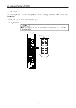
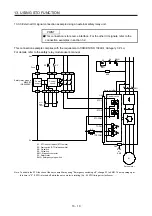
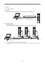
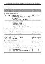
(1) Single axis
Operate the single-axis servo amplifier. It is recommended to use the following cable.
To RS-232C
connector
Servo amplifier
Personal computer
RS-422/232C conversion cable
DSV-CABV (Diatrend)
10 m or less
CN3
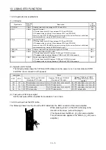
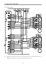
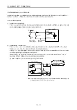
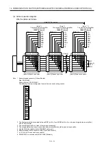
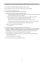
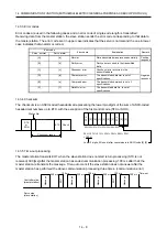
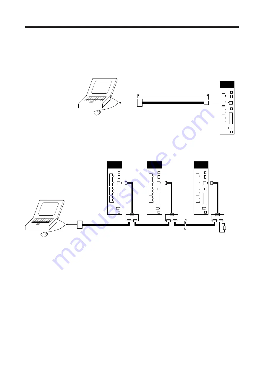
(2) Multi-drop connection
(a) Diagrammatic sketch
Up to 32 axes of servo amplifiers from stations 0 to 31 can be operated on the same bus.
To RS-232C
connector
RS-422/232C conversion cable
DSV-CABV (Diatrend)
Personal computer
(Note 1)
(Note 2)
(Note 1)
(Note 1)
Servo amplifier
CN3
Servo amplifier
CN3
Servo amplifier
CN3
Note 1. The BMJ-8 (Hachiko Electric) is recommended as the branch connector.
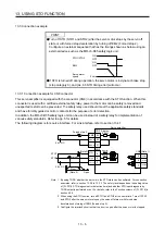
2. The final axis must be terminated between RDP (pin No. 3) and RDN (pin No. 6) on the receiving side (servo amplifier) with a
150
Ω
resistor.
Summary of Contents for MR-J4-100A(-RJ)
Page 19: ...10 MEMO ...
Page 75: ...1 FUNCTIONS AND CONFIGURATION 1 56 MEMO ...
Page 83: ...2 INSTALLATION 2 8 MEMO ...
Page 159: ...3 SIGNALS AND WIRING 3 76 MEMO ...
Page 203: ...4 STARTUP 4 44 MEMO ...
Page 351: ...7 SPECIAL ADJUSTMENT FUNCTIONS 7 40 MEMO ...
Page 365: ...8 TROUBLESHOOTING 8 14 MEMO ...
Page 387: ...9 DIMENSIONS 9 22 MEMO ...
Page 403: ...10 CHARACTERISTICS 10 16 MEMO ...
Page 553: ...12 ABSOLUTE POSITION DETECTION SYSTEM 12 30 MEMO ...
Page 567: ...13 USING STO FUNCTION 13 14 MEMO ...
Page 607: ...14 COMMUNICATION FUNCTION MITSUBISHI ELECTRIC GENERAL PURPOSE AC SERVO PROTOCOL 14 40 MEMO ...
Page 639: ...15 USING A LINEAR SERVO MOTOR 15 32 MEMO ...
Page 767: ...18 MR J4 03A6 RJ SERVO AMPLIFIER 18 84 MEMO ...
Page 856: ...APPENDIX App 41 ...
Page 905: ...MEMO ...


