
19. MR-D01 EXTENSION I/O UNIT
19 - 40
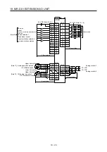
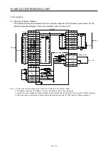
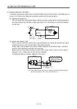
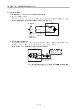
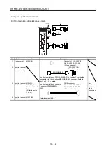
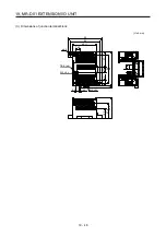
(5) Source I/O interface
In this servo amplifier, source type I/O interfaces can be used.
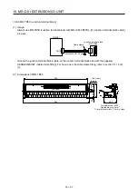
(a) Digital input interface DI-1
This is an input circuit in which the anode of the photocoupler is the input terminal. Transmit signals
from a source (open-collector) type transistor output, relay switch, etc.
Approx.
5.6 k
Ω
24 V DC ± 10%
800 mA
Switch
For transistor
SON
etc.
MR-D01
DOCOMD
Approximately
5 mA
V
CES
≤
1.0 V
I
CEO
≤
100 µA
TR
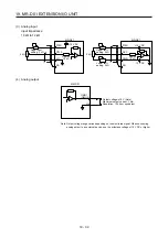
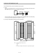
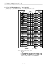
(b) Digital output interface DO-1
This is a circuit in which the emitter of the output transistor is the output terminal. When the output
transistor is turned on, the current will flow from the output terminal to a load.
A maximum of 2.6 V voltage drop occurs in the servo amplifier.
(Note) 24 V DC ± 10%
800 mA
MR-D01
INP
etc.
DOCOMD
Load
If polarity of diode is
reversed, servo amplifier
will malfunction.
Note. If the voltage drop (maximum of 2.6 V) interferes with the relay operation, apply a
high voltage (maximum of 26.4 V) from an external source.
Summary of Contents for MR-J4-100A(-RJ)
Page 19: ...10 MEMO ...
Page 75: ...1 FUNCTIONS AND CONFIGURATION 1 56 MEMO ...
Page 83: ...2 INSTALLATION 2 8 MEMO ...
Page 159: ...3 SIGNALS AND WIRING 3 76 MEMO ...
Page 203: ...4 STARTUP 4 44 MEMO ...
Page 351: ...7 SPECIAL ADJUSTMENT FUNCTIONS 7 40 MEMO ...
Page 365: ...8 TROUBLESHOOTING 8 14 MEMO ...
Page 387: ...9 DIMENSIONS 9 22 MEMO ...
Page 403: ...10 CHARACTERISTICS 10 16 MEMO ...
Page 553: ...12 ABSOLUTE POSITION DETECTION SYSTEM 12 30 MEMO ...
Page 567: ...13 USING STO FUNCTION 13 14 MEMO ...
Page 607: ...14 COMMUNICATION FUNCTION MITSUBISHI ELECTRIC GENERAL PURPOSE AC SERVO PROTOCOL 14 40 MEMO ...
Page 639: ...15 USING A LINEAR SERVO MOTOR 15 32 MEMO ...
Page 767: ...18 MR J4 03A6 RJ SERVO AMPLIFIER 18 84 MEMO ...
Page 856: ...APPENDIX App 41 ...
Page 905: ...MEMO ...


