

5. PARAMETERS
5 - 51
No./symbol/
name
Setting
digit
Function
Initial
value
[unit]
Control
mode
P S T
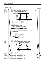
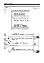
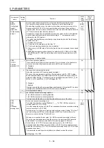
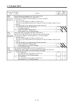
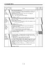
PC37
VCO
Analog speed
command
offset/
Analog speed
limit offset
Set the offset voltage of VC (Analog speed command).
For example, if CCW rotation or positive direction travel is provided by switching on
ST1 (Forward rotation start) while applying 0 V to VC, set a negative value.
When automatic VC offset is used, the automatically offset value is set to this
parameter. (Refer to section 4.5.4.)
The initial value is provided before shipment by the automatic VC offset function on
condition that the voltage between VC and LG is 0 V.
Setting range: -9999 to 9999
The value
differs
depending
on the
servo
amplifiers.
[mV]
Set the offset voltage of VLA (Analog speed limit).
For example, if CCW rotation or positive direction travel is provided by switching on
RS1 (Forward rotation selection) while applying 0 V to VLA, set a negative value.
When automatic VC offset is used, the automatically offset value is set to this
parameter. (Refer to section 4.5.4.)
The initial value is provided before shipment by the automatic VC offset function on
condition that the voltage between VLA and LG is 0 V.
Setting range: -9999 to 9999
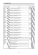
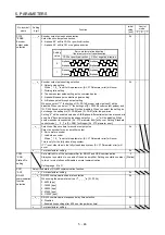
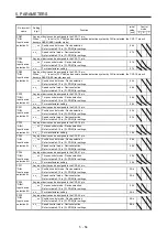
PC38
TPO
Analog torque
command
offset/
Analog torque
limit offset
Set the offset voltage of TC (Analog torque command).
Setting range: -9999 to 9999
0
[mV]
Set the offset voltage of TLA (Analog torque limit).
Setting range: -9999 to 9999
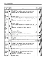
PC39
MO1
Analog
monitor 1
offset
Set the offset voltage of MO1 (Analog monitor 1).
Setting range: -9999 to 9999
0
[mV]
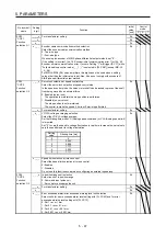
PC40
MO2
Analog
monitor 2
offset
Set the offset voltage of MO2 (Analog monitor 2).
Setting range: -9999 to 9999
0
[mV]
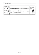
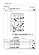
PC43
ERZ
Error
excessive
alarm level
Set an error excessive alarm level.
You can change the setting unit with "Error excessive alarm/error excessive warning
level unit selection" in [Pr. PC24].
Set this per rev. for rotary servo motors and direct drive motors. Setting "0" will be "3
rev", and setting over 200 rev will be clamped with 200 rev. Set this per mm for
linear servo motors. Setting "0" will be 100 mm.
Setting range: 0 to 1000
0
[rev]/
[mm]
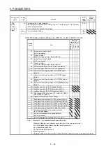
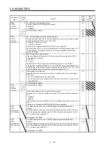
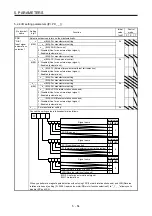
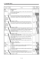
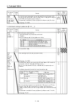
PC44
*COP9
Function
selection C-9
_ _ _ x For manufacturer setting
0h
_ _ x _
0h
_ x _ _
0h
x _ _ _ Load-side encoder cable communication method selection
Select the communication method of the encoder cable to be connected to the CN2L
connector of MR-J4-_A_-RJ.
0: Two-wire type
1: Four-wire type
When using a load-side encoder of A/B/Z-phase differential output method, set "0".
Incorrect setting will trigger [AL. 70] and [AL. 71]. Setting "1" while using a servo
amplifier other than MR-J4-_A_-RJ will trigger [AL. 37].
This digit is not available with MR-J4-03A6(-RJ) servo amplifiers.
0h
Summary of Contents for MR-J4-100A(-RJ)
Page 19: ...10 MEMO ...
Page 75: ...1 FUNCTIONS AND CONFIGURATION 1 56 MEMO ...
Page 83: ...2 INSTALLATION 2 8 MEMO ...
Page 159: ...3 SIGNALS AND WIRING 3 76 MEMO ...
Page 203: ...4 STARTUP 4 44 MEMO ...
Page 351: ...7 SPECIAL ADJUSTMENT FUNCTIONS 7 40 MEMO ...
Page 365: ...8 TROUBLESHOOTING 8 14 MEMO ...
Page 387: ...9 DIMENSIONS 9 22 MEMO ...
Page 403: ...10 CHARACTERISTICS 10 16 MEMO ...
Page 553: ...12 ABSOLUTE POSITION DETECTION SYSTEM 12 30 MEMO ...
Page 567: ...13 USING STO FUNCTION 13 14 MEMO ...
Page 607: ...14 COMMUNICATION FUNCTION MITSUBISHI ELECTRIC GENERAL PURPOSE AC SERVO PROTOCOL 14 40 MEMO ...
Page 639: ...15 USING A LINEAR SERVO MOTOR 15 32 MEMO ...
Page 767: ...18 MR J4 03A6 RJ SERVO AMPLIFIER 18 84 MEMO ...
Page 856: ...APPENDIX App 41 ...
Page 905: ...MEMO ...


