


19. MR-D01 EXTENSION I/O UNIT
19 - 11
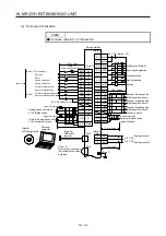
19.4 Installation direction and clearances
CAUTION
The equipment must be installed in the specified direction. Otherwise, it may
cause malfunction.
Leave specified clearances between the servo amplifier and cabinet walls or other
equipment. Otherwise, it may cause malfunction.
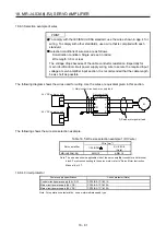
(1) Installation clearances of the servo amplifier
(a) Installation of one servo amplifier
40 mm
or more
10 mm
or more
10 mm
or more
(Note 2)
40 mm
or more
(Note 1)
Servo
amplifier
Cabinet
Cabinet
80 mm or more
Wiring allowance
Top
Bottom
Note 1. For the 11 kW to 22 kW servo amplifiers, the clearance between the bottom and the ground will be 120 mm or more.
2. To install the MR-J4-500A-RJ, leave a clearance of 25 mm or more between the left side and the wall.
Summary of Contents for MR-J4-100A(-RJ)
Page 19: ...10 MEMO ...
Page 75: ...1 FUNCTIONS AND CONFIGURATION 1 56 MEMO ...
Page 83: ...2 INSTALLATION 2 8 MEMO ...
Page 159: ...3 SIGNALS AND WIRING 3 76 MEMO ...
Page 203: ...4 STARTUP 4 44 MEMO ...
Page 351: ...7 SPECIAL ADJUSTMENT FUNCTIONS 7 40 MEMO ...
Page 365: ...8 TROUBLESHOOTING 8 14 MEMO ...
Page 387: ...9 DIMENSIONS 9 22 MEMO ...
Page 403: ...10 CHARACTERISTICS 10 16 MEMO ...
Page 553: ...12 ABSOLUTE POSITION DETECTION SYSTEM 12 30 MEMO ...
Page 567: ...13 USING STO FUNCTION 13 14 MEMO ...
Page 607: ...14 COMMUNICATION FUNCTION MITSUBISHI ELECTRIC GENERAL PURPOSE AC SERVO PROTOCOL 14 40 MEMO ...
Page 639: ...15 USING A LINEAR SERVO MOTOR 15 32 MEMO ...
Page 767: ...18 MR J4 03A6 RJ SERVO AMPLIFIER 18 84 MEMO ...
Page 856: ...APPENDIX App 41 ...
Page 905: ...MEMO ...


