


Synergy Q/MD Engineering Manual (v9.1 MD)
Custom Controls • 10–11
Programming Control Panel Functions
Use the following procedure to program a custom control button with basic functions:
1. Navigate to the
Custom Controls Menu 1-2
as follows:
•
Press
HOME
B
Custom Controls
.
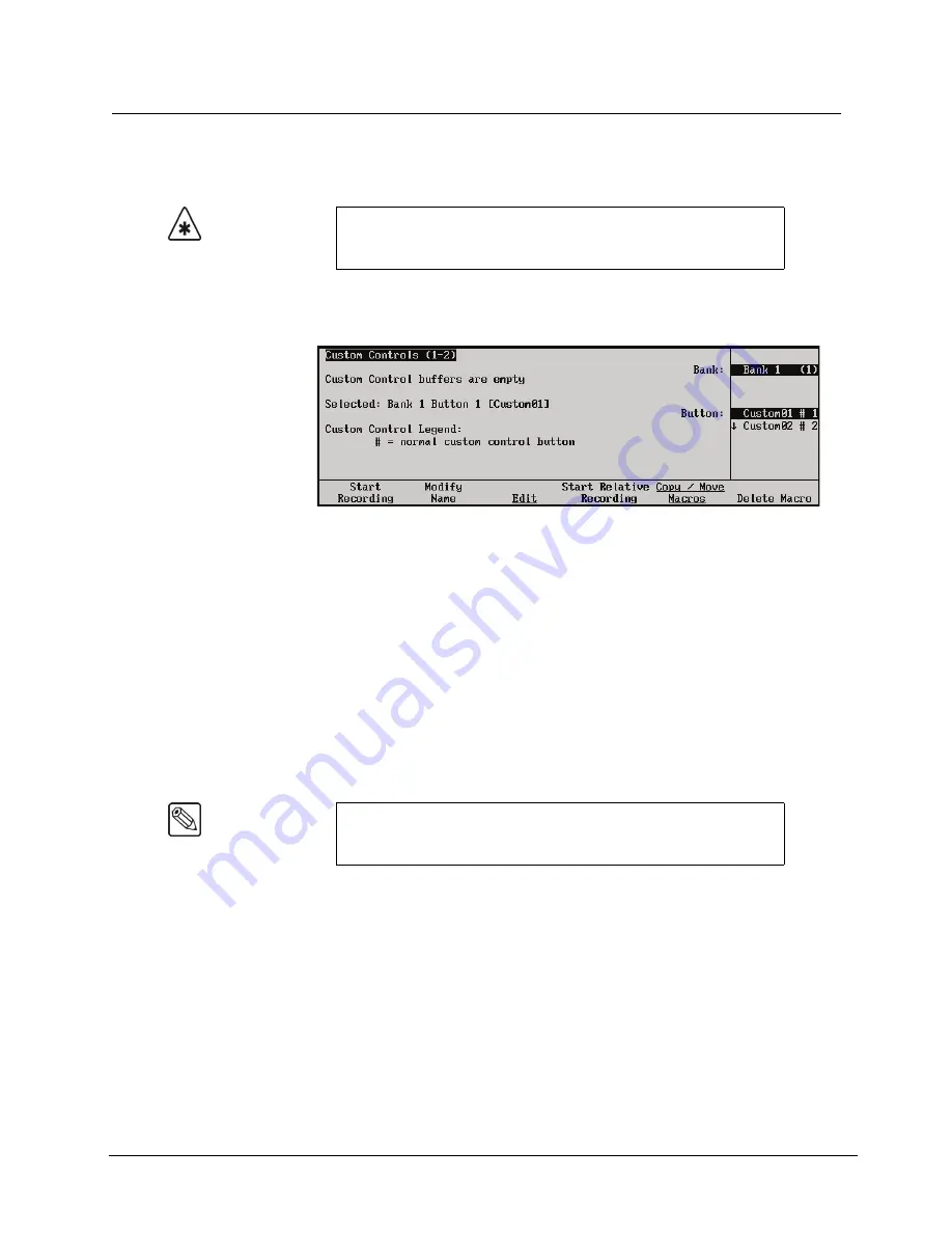
Custom Controls Menu 1-2
The
Main Area
provides the status of the Custom Control buffer, as well as the name
and status of the custom control selected on the menu. If you have
already
programmed
one or more macros, a percentage value is displayed that indicates how “full” the buffers
are.
The
Scroll Area
provides lists of the enabled banks, and a full list of custom control
buttons. Not
all
of the
custom control buttons exist on every control panel.
2. Select the Custom Control bank and button that you want to record to as follows:
•
Use the
Bank
knob
to select the custom control bank that you want to record the
custom control on.
•
Use the
Button
knob
to select the custom control button that you wish to program.
You can also press the button
directly
on the panel.
Important
Memory recalls from custom controls will override the current Effects
Dissolve, Keys Only, and Auto Recall settings to whatever settings
were in place when the custom control was recorded.
Note
Buttons with an asterisk (
*
) next to them in the list are
already
programmed, however, they can be edited. Refer to the section
“
” on page 10-42 for details.
Содержание Synergy MD
Страница 1: ...Ross Video Limited Synergy Q MD Engineering Manual Volume I Software Issue 9 1 MD ...
Страница 10: ......
Страница 18: ...viii Contents Synergy Q MD Engineering Manual v9 1 MD ...
Страница 46: ...1 28 Introduction Synergy Q MD Engineering Manual v9 1 MD ...
Страница 204: ...7 34 BNC Configuration and Check Synergy Q MD Engineering Manual v9 1 MD ...
Страница 302: ...10 56 Custom Controls Synergy Q MD Engineering Manual v9 1 MD ...
Страница 366: ...13 16 SmartConversion Synergy Q MD Engineering Manual v9 1 MD ...
Страница 370: ...GL 4 Glossary of Terms Synergy Q MD Engineering Manual v9 1 MD ...