516
Performance Characteristics
Appendix A
Servo Drive's Response Time for Commands from the CPU Unit
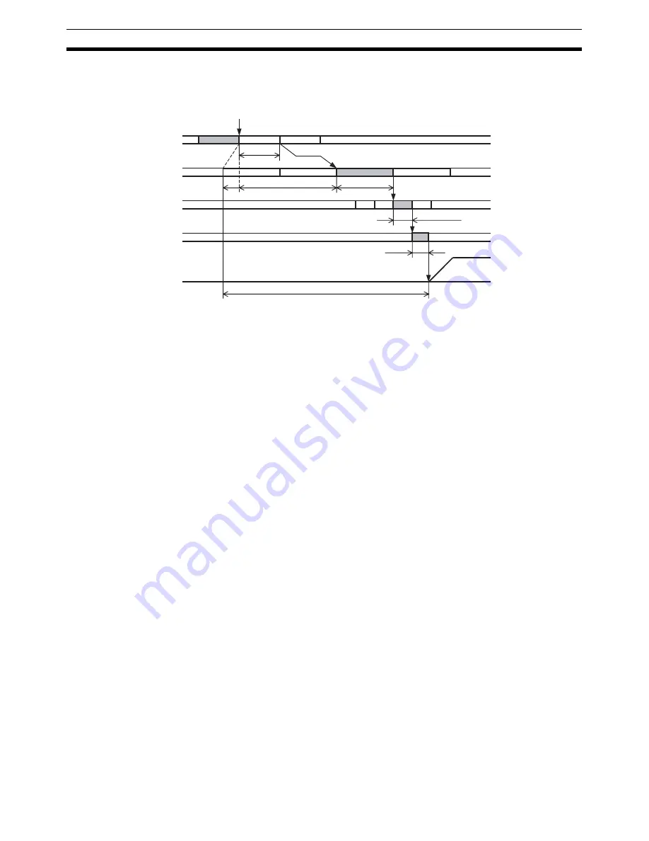
The response time starts with refreshing outputs for the cycle in which the command was sent from the CPU
Unit and continues until the Servo Drive starts operating in response to the command.
The maximum time from the end refresh of the user program's cycle in which the command was sent until the
command is actually received by the PCU is indicated as T
OUT_REF
:
(CPU cycle time or MECHATROLINK communications cycle, whichever is longer) + communications cycle
×
1
The PCU processing time from when the command is received by the PCU until it is sent using MECHA-
TROLINK communications is indicated as T
NC
:
MECHATROLINK communications cycle
×
1
Note
If a warning occurs, PCU retry processing is required, so the value for T
NC
is the MECHATROLINK com-
munications cycle
×
3.
The time for a command sent from the PCU using MECHATROLINK communications to reach the Servo Drive
is indicated as T
MLK
:
MECHATROLINK transfer cycle
×
1
The processing time until execution of the command received by the Servo Drive is indicated as T
SRV_OUT
:
250
μ
s (using an R88D-GN
@
-ML2 to send commands relating to interpolation feed, speed control and
torque control)
1,250
μ
s (using an R88D-GN
@
-ML2 to send commands other than those described above)
625
μ
s (using an R88D-WT
@
and FNY-NS115 or the SMARTSTEP Junior)
425
μ
s (using an R88D-KN
@
-ML2 or an R88D-WN
@
-ML2)
The maximum value for the time until the Servo Drive actually starts operating in response to the command
sent from the CPU Unit's user program, as indicated by T
CMD
, is calculated as the total of these values, as fol-
lows:
T
CMD(MAX)
= T
OUT_REF
+ T
NC
+ T
MLK
+ T
SRV_OUT
Note
T
CMD
varies depending on the width of T
OUT_REF
.
CPU Unit cycle time
PCU processing
T
NC
= Communications cycle
T
MLK
=
Transfer cycle
T
SRV_OUT
T
OUT_REF
CPU
→
NC
T
CMD
Cycle time
MECHATROLINK
communications
cycle
Servo Drive processing
Servo Drive operation
(e.g., axis operation)
Command sent
Содержание CJ1W-NC271 - 12-2009
Страница 2: ......
Страница 4: ...iv ...
Страница 6: ...vi ...
Страница 22: ...xxii ...
Страница 58: ...30 Starting Operation Section 2 2 ...
Страница 244: ...216 Axis Operating Input Memory Areas Section 4 8 ...
Страница 264: ...236 Transferring Servo Parameters Section 5 3 ...
Страница 396: ...368 Linear Interpolation Section 9 7 ...
Страница 648: ...620 List of Error Codes Appendix D ...
Страница 674: ...646 Additional Functions for the CJ1W NCF71 MA Appendix F ...
Страница 684: ...656 Index ...
Страница 686: ...658 Revision History ...


